


Contributing Writer
Because of its inherent corrosion resistance, austenitic stainless steel has become a cost-effective, staple material for long-term applications in many industries, such as petrochemical, food processing, and transportation.
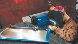
Also known as 300 series, austenitic stainless steel poses distinct challenges when it's joined with gas tungsten arc welding (GTAW), the most difficult of which are carbide precipitation and distortion. Good heat control, correct travel speeds, and adequate gas coverage are keys to avoiding these pitfalls.
Austenitic stainless steel is a poor conductor of heat. The presence of nickel (6 percent to 22 percent) and chromium (16 percent to 26 percent) enhances its corrosion and stain resistance, but these and other elements—often titanium and molybdenum—also cause it to react to heat differently from the way other materials react. Austenitic stainless steel conducts heat at about half the rate of mild steel, but has a much higher rate of thermal expansion when welded.
Typically, austenitic stainless steel requires a DC power source and pointed tungsten (any type except pure) for GTAW. It is similar to aluminum in that you should remove any oil, paint, and dirt before welding. It is different from aluminum in that you do not need to use a wire brush on it before welding. However, you should use a wire brush on the material between welding passes to remove potential interpass oxides. Use a stainless steel wire brush designated for this purpose.
Filler rod is recommended on applications with a base material thicker than 18 gauge, but this recommendation is contingent on joint design. For example, an outside corner might not require filler rod, but an inside joint does.
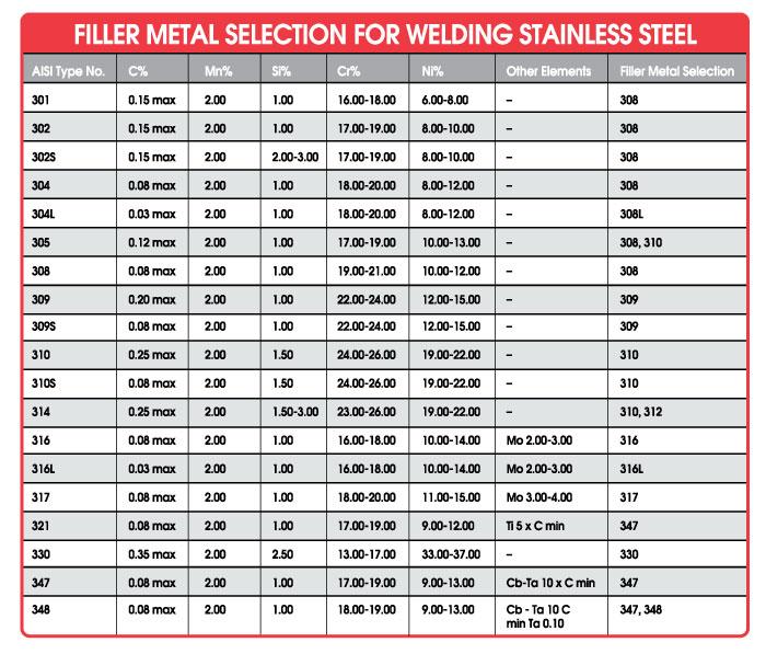
Most GTAW applications require overmatching the filler rod—that is, the filler rod should have higher strength properties than the workpiece. For example, on 304 series austenitic stainless steel, you should use an ER308 rod (see Figure 1 for additional options and exceptions). Typically, austenitic stainless steel filler rod is available in diameters from 0.035 to 5/32 inch (0.9 to 4.0 mm) and chosen according to the joint design, welding parameters, and application.
One of the biggest pitfalls to avoid is carbide precipitation.
Carbide precipitation occurs when the chrome and carbon in the austenitic stainless steel are drawn out of the material and react to the atmosphere. It occurs between 800 and 1,400 degrees F (426 and 760 degrees C), so you need to keep the weld zone temperature below 800 degrees. Alternatively, you can weld with argon as the shielding gas.
Austenitic stainless steel is easy to read when welded: A good weld is straw-colored. It is likewise easy to detect carbide precipitation: The metal turns black. Material that turns blue or purple indicates possible carbide precipitation.
The three main culprits responsible for carbide precipitation are too much heat, too slow travel speed, and inadequate shielding.
Heat and Travel Speed. The best defense against carbide precipitation is practice and a few key guidelines. One, remember the rule of amperages: Use 1 amp of welding current for every thousandth of an inch of material thickness. Two, maintain an appropriate travel speed to prevent too much heat in the weld zone.
In addition to practice, you should look for the "devil's eye." This is the fluid dot in the center of the weld puddle that is formed by foreign (but not worrisome) elements that continuously swirl around in the center of the weld puddle. The presence of the devil's eye is insurance that not only is travel speed appropriate, but also that other factors, such as torch angle, filler rod position, penetration, and root opening, are optimal.
Gas Coverage. Using the appropriate type and amount of shielding gas is another factor in preventing carbide precipitation. Typically, pure argon provides the best results when welding thin austenitic stainless steel, but adding a small amount of hydrogen is not uncommon when you need a faster travel speed, especially on thicker pieces or in an automated application.
A gas lens is recommended when using GTAW on austenitic stainless steel. A gas lens is a copper and brass component with layered stainless steel mesh screens. It replaces the collet body in a standard GTAW torch. The gas lens helps distribute gas more evenly around the tungsten, arc, and weld puddle and provides good cooling action.
Full-penetration welds require back-purging—covering the back of the weld with shielding gas. Back-purging protects the underside of the weld from atmospheric elements. You can use a commercial apparatus or fabricate a custom-made cover.
Finally, remember to maintain an adequate amount of postflow gas. The best practice is to maintain one second of postflow for every 10 amps of welding current.
Because it is prone to greater thermal expansion than other materials, austenitic stainless steel tends to distort easily. A current setting that is too high or a travel speed that is too slow can contribute to this problem. Thermal expansion occurs because the heat-affected zone (HAZ) on austenitic stainless steel is more localized than on other materials. When the weld cools, slow thermal transfer to the surrounding material leads to buckling.
Joint design and clamping are good defenses against distortion. The key to joint design is creating a joint that limits the number of weld passes required (especially on 1/4-in. and thicker austenitic stainless steel), and with it the amount of heat input. One way to limit these passes is to create a joint design consisting of a V-groove, modified V-groove, U-groove, or J-groove.
Another way to prevent distortion is to clamp the workpiece. Doing so is especially important on light-gauge material, as these pieces are more prone to buckling.
Hand in hand with distortion, not surprisingly, comes the potential for cracking, especially in the weld initiation and crater area. One way to prevent cracking is to use run-on and run-off tabs.
These tabs need to match the base material and can be used on automated or hand-held GTAW applications. They provide an area to "run on" or "run off" the weld by eliminating arc starting and stopping on the actual weld joint. They also aid in the complete filling of the crater area to help prevent cracking and are easily ground or cut off the weld after it cools.

The Fabricator is North America's leading magazine for the metal forming and fabricating industry. The magazine delivers the news, technical articles, and case histories that enable fabricators to do their jobs more efficiently. The Fabricator has served the industry since 1970.
start your free subscription
Easily access valuable industry resources now with full access to the digital edition of The Fabricator.

Easily access valuable industry resources now with full access to the digital edition of The Welder.

Easily access valuable industry resources now with full access to the digital edition of The Tube and Pipe Journal.

Easily access valuable industry resources now with full access to the digital edition of The Fabricator en Español.
In this episode of The Fabricator Podcast, Caleb Chamberlain, co-founder and CEO of OSH Cut, discusses his company’s...


