


Applications Engineer

Figure 1: Welding sensors must have rugged designs to stand up to the rigors of welding, where the arc temperature can reach as high as 10,000 degrees F, depending on the application.
Automated welding systems have proven ideal for applications in which the same task is done repeatedly. The same can’t be said for the many variations that occur in the real world of metal fabricating, however.
Inconsistencies in component dimensions, component positioning, joint alignment, edge preparation, metal chemistry, and surface conditions present substantial obstacles to basic machine welding that lacks sensory powers. Fortunately, adding sensors to the machines allows the torch head to adjust rapidly to the many variations found in metal fabrications.
A machine’s automation level (see Sensing in Machine Welding sidebar) is a reflection of how it incorporates sensors. Some sensors make machines “smarter”—better able to cope autonomously with variation. Other sensors enable people to operate machines more effectively .
If the variation in a procedure can be predicted accurately and categorized to a very large degree, a sensor probably can be employed to allow the machine to detect that variation and adjust as necessary. The more irregular the variables, the more likely it is that a human is required to operate the machine. In such applications, sensors may be used to facilitate the operator’s decision-making.
Commercial off-the-shelf sensor types include laser triangulation systems, machine vision cameras, welding cameras, thermographic cameras, process parameter monitors, arc sound detectors, and spectrophotometers. The first four tools fall under the category of vision sensors and have emerged as a proven way to boost quality efforts in welding applications.
However, metal fabricators should realize that not all vision-sensing products have proven themselves in the harsh world of welding. For example, variations in joint shape and metal reflectivity, as well as interference from arc emissions, can limit a sensor’s accuracy and repeatability. Vision sensors for welding generally require a robust design to stand up to process smoke, spatter, and radiation that can disturb visibility (see Figure 1).
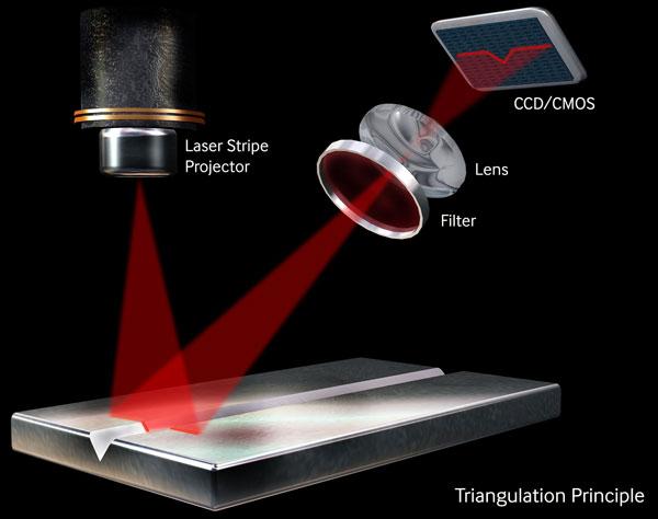
Laser triangulation, or a 3-D sensor, relies on the principles of triangulation to rapidly and precisely derive the important characteristics of the feature to be measured or inspected. These sensors integrate a camera that uses either a charge-coupled device or complementary metal oxide semiconductor technology to create the digital images and a structured light source within a common housing. The sensor projects one or more precision-focused lines of laser light onto the feature surface below (see Figure 2).
The use of a laser to illuminate the feature ensures that measurements are not affected by changes in ambient lighting conditions. Where the laser line strikes a surface, it forms a contour line or profile of the feature. The sensor’s integrated imager then views the contour line’s shape and position within its high-resolution pixel array, and accurate Y (cross-profile) and Z (height) coordinates are derived through triangulation.
The 3-D sensor system uses dedicated processing and inspection algorithms to create electronic profiles from the raw sensor data, and then measurements are taken from the electronic profiles. Depending on the intended application, numerous limits or thresholds can be set and compared against the profile data. When thresholds are exceeded, alarm conditions are triggered, allowing prompt corrective action to be taken.
The 3-D sensors are suitable for use with repetitive, highly automated fusion welding processes, including gas metal arc, gas tungsten arc, submerged arc, laser beam, and hybrid welding. They also occasionally are used in friction stir welding.
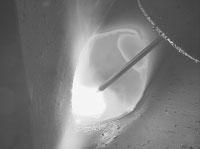
Figure 3: Besides giving the operator a clear view of the welding process, the video from a welding camera can be recorded for troubleshooting, training, or quality assurance purposes.
When located in front of the welding torch, 3-D sensors are used for horizontal seam tracking and vertical torch height control. Measurements of key joint parameters are made and sent to the machine controller to help keep the torch in the correct position for welding regardless of changes in the joint’s position. The 3-D sensor also may be used to measure joint geometry prior to welding to ensure correct fit-up and for adaptive control of weld parameters or weave profile based on changes in the joint gap or volume.
The 3-D sensors also may be positioned behind the weld process for postweld inspection of the weld. Given the triangulation sensor’s ability to work in three dimensions, it can measure weld bead height and width as well as defects, such as concavity or convexity in the weld bead, undercut, porosity, burn-through, and missing welds.
Machine vision cameras, commonly found in many manufacturing processes, send visual information to a computer for analysis. For welding applications, their use is restricted to pre- and postwelding inspection because they typically do not provide a meaningful image of the weld pool or adjust to the large variation in light between nonwelding and welding conditions. In-process visual monitoring of welding is accomplished with welding cameras.
In prewelding inspection, machine vision technologies are used to locate and identify joints or components for positioning purposes. A camera mounted to the top frame of a robotic cell can capture the preweld assembly shape for comparison to a reference shape, ensuring that components are in the correct position and clamps are locked before welding. A camera mounted near a torch-cleaning station of a robotic cell may be used to check and adjust the tool center point after cleaning and prior to the start of a weld.
Machine vision cameras also may be used for postweld inspection of the weld surface, such as for the verification of the completed weld. Compared to laser triangulation sensors, machine vision cameras have difficulty measuring height. However, machine vision cameras may be used to automate liquid penetrant or visual inspection. Grayscale image analysis is used to determine whether an indication is outside of specification. In comparison to the equivalent manual inspection technique, such technology may be used to record the inspection results permanently.
In contrast to machine vision cameras, welding cameras are designed to provide a meaningful in-process image of welding. Through advances in sensor technology, welding cameras are capable of producing an image similar to that observed by a human eye through a welding helmet. The operator is provided with an image in which the weld pool and background are simultaneously clear. Welding cameras, as a result, serve as the operator’s eyes where it’s impossible, dangerous, or too costly for a human to observe the welding process directly.
Some of the mechanized welding applications these types of cameras are useful for include welding internal pipe seams, cladding internal pipes, welding in nuclear facilities, welding the sides of large ships and tanks, narrow gap welding, and orbital welding. The magnified view of the proc-ess also is useful in microwelding applications in which the welds are too small to be observed easily or as an operator’s eyesight wanes.
A welding camera facilitates monitoring of the welding process, including the location of the torch relative to the joint, the position and melting behavior of the wire feed, and the arc shape, which serves as a broad indicator of processing performance.
A clear view of the weld pool from the front or back also allows an experienced operator to detect a number of defects (see Figure 3). For example, to eliminate lack of fusion defects, the operator must ensure that the joint edges are sufficiently melted and that the weld pool does not run ahead of the arc and fill the weld groove.
For many applications, the welding camera must also be able to provide a clear image when welding is not taking place. Prewelding, the image may be used for setting up the process. For instance, the image could be used to ensure that the electrode is correctly positioned relative to the weld seam and that the wire feed is correctly located. Postwelding, the image may be used for visual inspection of the top surface of the weld.
A digital image of the weld pool or weld seam also may be processed by a computer as part of an automated quality monitoring system, akin to machine vision. Such technology is currently available only as a commercial off-the-shelf sensor for laser welding. In laser welding applications, the welding camera is coaxial with the laser beam, and a computer analyzes the image. Weld pool width, length, keyhole diameter, and the keyhole position relative to the weld pool are determined and used to assess weld quality and process stability.
While the sensors discussed previously may be used for detection of many surface weld defects, the detection of subsurface defects requires different sensors and is usually carried out postwelding, typically by ultrasonic or X-ray inspection. However, in-process inspection of subsurface weld defects can be achieved with eddy current testing or infrared imaging, also known as thermography.
All objects emit electromagnetic radiation, which can be detected by an infrared camera. The amount of electromagnetic radiation emitted by an object increases with temperature, so a temperature profile of a solidifying weld can be determined from an infrared image. By identifying regions of inconsistent cooling or instability, thermography may be used as a real-time method for detecting subsurface defects such as lack of penetration.
Electromagnetic radiation from the arc and tungsten os known to interfere with the measurement of the base metal temperature, but methods have been developed to deal with this issue. Thermal imaging has been employed to monitor safety-critical welding applications found in the automotive and tube and pipe industries.
Sensing in Machine Welding
Welding automation can be broken down into three categories:
Source: “What is the function of sensing in machine welding?” TWI Ltd., Cambridge, United Kingdom.


The Fabricator is North America's leading magazine for the metal forming and fabricating industry. The magazine delivers the news, technical articles, and case histories that enable fabricators to do their jobs more efficiently. The Fabricator has served the industry since 1970.
start your free subscription
Easily access valuable industry resources now with full access to the digital edition of The Fabricator.

Easily access valuable industry resources now with full access to the digital edition of The Welder.

Easily access valuable industry resources now with full access to the digital edition of The Tube and Pipe Journal.

Easily access valuable industry resources now with full access to the digital edition of The Fabricator en Español.
In this episode of The Fabricator Podcast, Caleb Chamberlain, co-founder and CEO of OSH Cut, discusses his company’s...


