


President
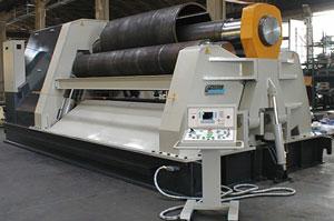
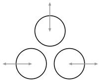
Figure 1: Three-roll bending machines are just one of many plate rolling machine styles available to metal fabricators.
The best way to determine the best plate or sheet rolling machine (see Figure 1) for the job is to find out what various machines can do. By obtaining this information, you can properly size and select a machine to fit your particular bending application.
Of course, for more in-depth information and application engineering expertise, you can contact plate or sheet metal rolling equipment experts directly.
Plate or sheet bending rolls are offered in two distinct categories: single and double-pinch, but they may vary in geometry or style. General machine styles are three-roll initial-pinch, three-roll double-pinch, four-roll double pinch, three-roll variable translating, three-roll pyramid, and two-roll systems. Plate rolls are also built in a vertical format for special applications. Matching the most appropriate machine style to the application is important.
Machine capacity is equally if not more important than style. Plate roll manufacturers commonly rate their machines according to baseline material yield strengths of 36,000 to 38,000 pounds per square inch (PSI). However, you need to realize that steel mills are producing materials with ever-increasing yields. When choosing a machine, you must refer to your mill certificates and verify the average yield strength of the plate you are buying. It is not uncommon to find that the “mild“ steel you are rolling will have actual yields in the 48,000- to 58,000-PSI range. Remember, machine capacity must match your material, and most plate roll manufacturers can provide detailed capacity-versus-yield tables to assist you.
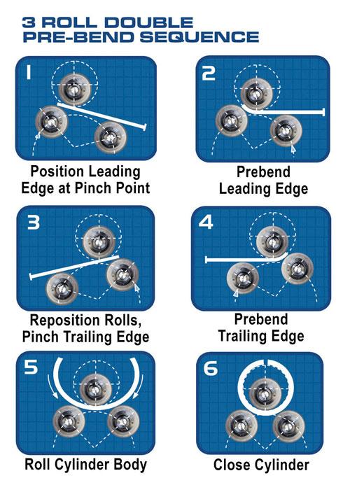
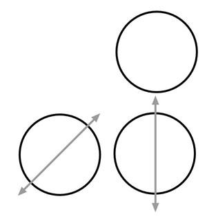
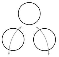
You often will see capacities for both prebending and rolling for any plate rolling machine. Prebending is performed on the plate roll at the leading and trailing edges of the sheet (see Figure 2)—and eventually the seam (see Figure 3).
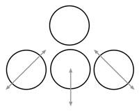
A sheet cannot physically be bent right to the edge, and thus what remains is referred to as the unbent flat (see Figure 4). The minimum flat you can expect is 1.5 times the material thickness and often 2.5 to 3.5 times the material thickness for heavier plate.
It is the prebending operation, in attempting to minimize the unbent flat, which takes the most power. That’s why prebending ratings are lower than rolling capacities for any given machine.
You must be mindful when reviewing machine capacities that the maximum rolling capacity is usually expressed with the basic requirement of multiple rolling passes and very long unbent flats. You also must note the material thickness and width and equipment characteristics such as cylinder diameter, machine type, yield, and diameter of rolls. Operator proficiency also should be taken into consideration.
NCs and CNCs are becoming more common in the workplace. Most NC and CNC machines are four-roll types.
Automated controls are recommended for high-volume cylinder or shell production and to roll complex shapes that are not easily reproduced using standard manual controls. Multiple bends, variable-radius bends, and ovals are common examples of these complex shapes.
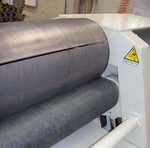
Figure 3: If the prebending is done correctly, the seam should come together nicely.
Three-roll initial-pinch (see Figure 5) or single initial-pinch plate rolls generally are for light-capacity applications and may be electromechanical or hydraulic. They work by pinching the flat sheet between two vertically opposed rolls while the third, offset roll—or bending roll—moves upward to contact and then bend the sheet. When rotation of the rollers is activated, the sheet exits at a given radius. With the sheet cut to the developed length and the bending roll properly positioned, the part is rolled into a cylindrical shape that can then be welded at the seam to produce a closed cylinder.
When a cylinder is completely rolled, it is extracted from the top roll. Machines generally are equipped with some type of top roll release mechanism that allows for the cylinder’s extraction. This extraction is accomplished with the help of a forward-tilting or forward-releasing top roll or a removable end yoke.
In most applications, these machines require removal and reinsertion of the sheet to prebend both ends. They are cost-effective, but may be more labor-intensive in a production setting than their modern counterparts.
Many large, mechanical initial-pinch machines were built during the 1950s and may occasionally be found on the used market. All have cast frames, as modern alloys and welding techniques had yet to be invented.
Double-pinch plate rolls are available in light to very heavy capacities and can have three (see Figure 6) or four rolls (see Figure 7). The terminology can be confusing as these units also may be referred to as double-pinch pyramid plate rolls or double-initial-pinch plate rolls. Both three- and four-roll styles have fixed-position top rolls and two offset, or lateral, rolls, one on each side.
The four-roll styles have an additional roller underneath the top roll, which constantly pinches the plate during rolling. Double-pinch rolls can prebend both plate ends without removal, as is required with single-pinch rolls.
Three-roll machines generally require prebending the leading end, running the sheet through the machine to prebend the trailing end, and then switching roll rotation direction to roll the cylinder body. Four-roll plate rolls have a slight advantage in cycle time because they permit prebending of the leading edge, rolling the cylinder body, and finishing off the trailing prebend, all while rolling in the same direction.
Smaller machines can be mechanical, but most are hydraulic and include drop end yokes (see Figure 8) for easy extraction of the workpiece.
Four-roll plate rolls generally are the only equipment with NCs or CNCs because the fourth roll provides constant pinching action, minimizing the chance for slippage. Automatic controls use an encoder to track movement of the plate through the machine. If the plate slips, the bending roll movements will be out of synch with the rolling movement.
Variable-geometry three-roll plate rolls are not new, but are gaining in popularity around the world (see Figure 9). They are built to handle medium to extremely heavy plate rolling applications.
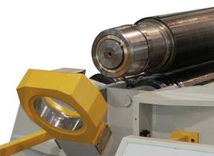
Figure 8: Easy-to-remove end yokes can make material removal a quick process.
The top roll moves up and down while the lower two rolls each move horizontally. This lower roll movement increases the offset distance from the top roll and in so doing delivers a distinct mechanical advantage in bending. A machine of this type works well over a wide range of material thicknesses.
With varying geometry, these rolls can be used like a single-pinch, double-pinch, or pyramid-style machine that requires minimal sheet movement during prebending. In the past these machines commonly were found in shipyards, but are now being placed in general job shop and manufacturing applications.
True pyramid machines are rarely used in cutting-edge facilities. They usually can be found on the used market.
They have three rolls (see Figure 10), with both lower rolls fixed in position and the top, or bending, roll moving up and down. In general, they leave a very long unbent flat and are not as user-friendly as other types of rolling machines.
Two-roll machines (see Figure 11) are designed for thin-gauge material rolled to reasonably small diameters. They use a large-diameter, urethane-coated pinch roller that moves up with extreme pressure against a small-diameter steel top roll. A mandrel or drum, very close in OD to the desired ID of the finished part, is fitted over the top roll.
Two-roll sheet rolls are extremely fast and will roll round parts even if the blank has cutouts or holes. Because they require a mandrel for each part diameter and material thickness, they are not as versatile as some other machines, but for dedicated high-speed production, they are often the absolute best choice.
In terms of optional equipment for rolling machines, the most important items to consider are hardened roll surfaces and cone rolling devices.
Today’s harder materials and laser/plasma cutting techniques require hard outer roll surfaces on rolling equipment. Look for a hardness rating from 50 to 55 Rockwell C scale. Hardness in this range will have a reasonable penetration depth and provide long-lasting protection against roll surface wear. Hardness exceeding 60 will have a shallow penetration and result in cracking or crazing of the roll surface.
Cone rolling devices, which permit you to roll a conical shape, are standard on some machines. Lateral material supports and overhead supports are also optional, but less frequently requested. Overhead supports prevent light materials from collapsing when rolled to large diameters. A side support can also assist in preventing light materials from recurving toward the floor if the radius is very large.
Some machines have extended roll shafts that protrude through the machine frame. Section or pipe dies can be fitted on these stub shafts, but it is not practical to roll angle iron on a plate roll. Angle tends to twist when rolled, and plate rolls do not have outboard, adjustable, lateral material guides to prevent this twist. You should consider using a section rolling machine or angle roll for that type of bending. In general, section dies on plate rolls are good for bending flat bar the hard way, rods, or small pipe.
Additionally, most new roll bending machines are equipped with modern safety devices such as emergency-stop buttons; safety trip wires; 24-VAC, low-voltage control circuitry; and detached operator control consoles. However, it remains the responsibility of the owner to ensure the installation and proper use of operation safety guards or devices.

The Fabricator is North America's leading magazine for the metal forming and fabricating industry. The magazine delivers the news, technical articles, and case histories that enable fabricators to do their jobs more efficiently. The Fabricator has served the industry since 1970.
start your free subscription
Easily access valuable industry resources now with full access to the digital edition of The Fabricator.

Easily access valuable industry resources now with full access to the digital edition of The Welder.

Easily access valuable industry resources now with full access to the digital edition of The Tube and Pipe Journal.

Easily access valuable industry resources now with full access to the digital edition of The Fabricator en Español.
In this episode of The Fabricator Podcast, Caleb Chamberlain, co-founder and CEO of OSH Cut, discusses his company’s...


