


Bending basics: Why profound-radius bending is a different animal
Be sure to account for significant springback and multibreakage
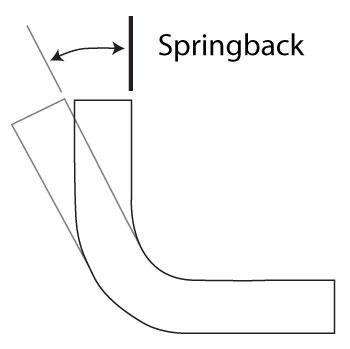
Figure 1: Springback is caused by the difference between tensile and compressive forces.
Large or profound-radius bends are those in which the inside bend radius exceeds eight times the material thickness, but is still too small to move to the plate roll. At that point, press brake operation becomes a different animal.
To begin with, you must account for a dramatic amount of springback. Springback occurs in bending as the material tries to return to its original flat position. This is caused by the difference between tensile forces on the bend’s outside surface, where the material is being expanded, and the compressive forces on the bend’s inside surface.
Because the tensile forces are greater than compressive forces, the material will pull back. In a bend with an inside radius that is closer to the material thickness, the springback is only a few degrees. With large bend radii, though, springback can be as much as 60 degrees, especially in newer high-strength steels (see Figure 1).
Springback Challenges
There are several ways to deal with these large springback amounts, starting with standard, time-honored tooling. Before the advent of precision-ground tooling, most press brake tooling was either a dedicated tool set for coining or bottoming (for example, a 135-degree die and a 45-degree punch, which was used to form a 45-degree-complementary bend); a straight-up 90-degree V die; or a channel or acute tool. This was before the 1980s, a time when “air forming” had yet to be defined.
When it came to the punches for large-radius bends, they were (and still are) usually made in-house from large-diameter barstock or thick-walled tubing. This led to a major problem: The dies were 90 degrees, and the round punches had an angle of 90 degrees, with one-quarter of the punch circumference contacting the workpiece during forming.
When the operator attempted to form the material, it was merely held in place at the points where the die, punch, and material interacted (see Figure 2). This meant that there was no way to deal with the springback except to manually force the angle through brute force from one or more operators—a very inconsistent proposition at best. The operator could have used a channel die, but these dies often weren’t deep enough to allow the punch to penetrate into the die space to bend the material to the required angle.
Some Tooling Relief
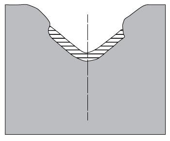
Precision-ground tooling offered something new: the relieved die. In this tool, the offending portions of the die are removed (see Figure 3).
The die has something else that older tools didn’t: varying die angles. Included die angles decrease with size: 90 degrees, then 88, 85, 78, 73, before moving into the acute realm of 45 and 30 degrees. Nowadays some dies are even offered with angles in between. Once upon a time, you couldn’t order an 89-degree tool off-the-shelf, but now you can.
Different die angles help push the material around the punch to compensate for springback. The larger the radius, the more material makes up that radius and the greater the springback. Because of clearance from the removed material in a relieved die, as well as the change of die angle, the punch can penetrate deep into the die space. Meanwhile, the top portion of the die (which isn’t relieved), near the die shoulders, pushes the material around the punch in the early portion of the forming process.
Multibreakage
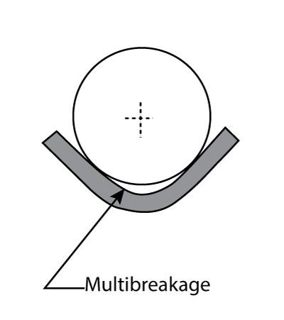
Precision-ground relieved dies allow the punch to bend the workpiece to the desired angle, but they don’t eliminate another element that becomes more pronounced in profound-radius bending: multibreakage. This is the leading radius that precedes the punch radius when the bend angle exceeds 90 degrees complementary. The greater the bend angle, the smaller the leading radius (see Figure 4).
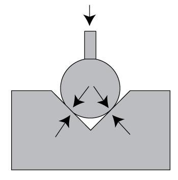
Figure 2: With a round punch on a standard V die, the material is simply held in place at the two contact points shown. There is no easy way to deal with springback..
It is possible to calculate the required punch diameter to achieve the desired bend radius, but this is difficult at best and generally requires several tests to achieve the desired result. And as we all know, if you have the wrong radius, you have an incorrect bend deduction; and if you have an incorrect bend deduction, the part isn’t being made to the print.
Urethane Pads
The answer lies in forcing the material against the punch radius. This can be accomplished by adding a spring-loaded steel bar in the bottom of the die—but this is an expensive and time-consuming proposition, especially considering that these tools are through-hardened to 70-75 Rockwell C. You probably want to avoid this cost, unless part production has very large volumes.
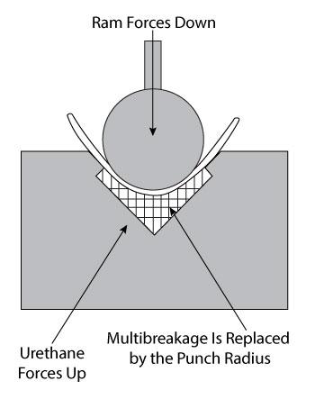
Alternatively, you can place a urethane pad in the bottom of the die. Urethane acts like a solid hydraulic: force something into it, and it pushes back with equal force on all surfaces that the urethane contacts (see Figure 5).
You will need a urethane pad, shaped to fit into a die (triangular for V dies), and long enough to exceed the bend length. These pads usually have a low durometer rating, a measure of the urethane’s hardness; 60 often is a good choice.
You can purchase these pads off-the-shelf, or you can make your own. A quick trip to your local hobby shop for the base and catalyst, and you’re on your way. Find some way to temporally seal the end of your die, gently mix the base and catalyst, and pour it into the die until it’s about a third full. In a matter of minutes, you have a urethane pad. Note that off-the-shelf pads are extruded and have better quality and consistency.
If this is not an option, you may want to try something as simple as a high-pressure water hose that’s cut to fit at the bottom of the die. Push the material into the rubber hose, the rubber hose pushes back, and the material will take on the radius of the punch.
In some situations you can replace a wide V die with a retainer box. The retainer box constrains the pad in the same way the V die does, except here the pad volume becomes a factor, as well as the loss of the air channel under the pad. Air channels allow the punch to penetrate deeper into the pad without needing excessive tonnage. The air channels are created with deflection bars of various sizes. The larger the bar, the larger the air channel—but note that this applies only to standard retainer boxes.
As the material is forced into the pad, the pad material on either side of the punch will push up and out of the retainer box, forcing the material around the punch and causing the material to take on the punch radius.
The pad itself must be at least 10 times the volume of the penetrating punch radius and material. If the urethane pad volume is too small, the pad will develop hysteresis. This buildup of internal heat within the urethane pad will cause it to disintegrate—obviously, not a good thing.
What About Bend Deductions?
Whether you form into a large-width V die with or without the benefit of some form of backup or pad, your bend deduction should be based on the achieved radius of the bend. As in all circumstances, the radius will relax some once the forming pressure is released. The effect should be nominal, though it may need to be taken into consideration in some cases.
Two Basic Issues
Profound-radius bending boils down to these two points: First, the larger the radius you have as compared to the material thickness, the greater the springback. Second, you need to factor in multibreakage—the radius that forms prior to the primary radius. If you account for both of these concepts, the different animal of profound-radius bending will become a lot more manageable.
About the Author

About the Publication

subscribe now

The Fabricator is North America's leading magazine for the metal forming and fabricating industry. The magazine delivers the news, technical articles, and case histories that enable fabricators to do their jobs more efficiently. The Fabricator has served the industry since 1970.
start your free subscription- Stay connected from anywhere

Easily access valuable industry resources now with full access to the digital edition of The Fabricator.

Easily access valuable industry resources now with full access to the digital edition of The Welder.

Easily access valuable industry resources now with full access to the digital edition of The Tube and Pipe Journal.

Easily access valuable industry resources now with full access to the digital edition of The Fabricator en Español.
- Podcasting

In this episode of The Fabricator Podcast, Caleb Chamberlain, co-founder and CEO of OSH Cut, discusses his company’s...
- Trending Articles
1
How to set a press brake backgauge manually

2
Capturing, recording equipment inspection data for FMEA

3
Tips for creating sheet metal tubes with perforations

4
Are two heads better than one in fiber laser cutting?

5
Hypertherm Associates implements Rapyuta Robotics AMRs in warehouse
