


Bending Basics: Why tonnage matters
Never—ever—exceed the load limits for your tooling or press brake
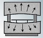
Figure 2: Deflection is the temporary deformation of the press brake ram and bed that occurs naturally under a load. An overtonnage situation can push a brake beyond its deflection limit, causing upset, where the ram and bed stay in a permanently deflected, or bent, state.
Selecting the press brake and tooling for a particular job involves much more than just making sure there’s enough brute force. Make one miscalculation, and pieces of tooling can fly while, at the same time, you may exceed the ram center load, causing the press brake ram and bed to bend. If you don’t believe this can happen, look at almost any high-mileage mechanical press brake and count the number of shims between the die and the bed.
To avoid these problems, take a look at your tonnage and load limits.
How Much Tonnage Does a Job Require?
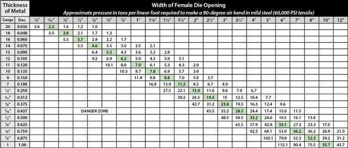
Start by looking at a standard tonnage chart (see Figure 1) that relates the workpiece thickness with the width of the die opening. Where the two intersect gives you the approximate tonnage per foot required for the job, based on 60,000-PSI tensile cold-rolled steel.
Tonnage charts can be inaccurate, though. So to find the tonnage a job requires quickly and accurately every time, consider using the following formula, which solves for tonnage per inch when air forming 60,000-PSI-tensile AISI 1035 cold-rolled steel over a given die width: Tonnage per inch = {[(575 × Material thickness2) / Die width] / 12}. Multiply this value by the bend length, and you’ll get the total tonnage required for the application.
Still, in any job shop, material types vary, and each has its own tensile strength. Tensile strength is defined as the ability of a material to bear weight without breaking or being pulled apart under a smooth load, not a sudden impact.
To incorporate different materials into the tonnage calculation, you include a material factor in the tonnage formula. Here are some common material factors:
- AISI 1035 cold-rolled steel = 1
- 304 Stainless = 1.4 to 6
- Aluminum 6061 T6 = 1.28
- Aluminum 5052 H32 = 0.50
We use the 60,000-PSI-tensile AISI 1035 (the most common type of cold-rolled steel used) as a baseline and so give it a value of 1. To obtain a factor for a specific material, you can perform a simple comparison of tensile strengths, working with 60,000-PSI tensile as the baseline. For example, if you’re working with a material with a specified maximum tensile strength of 120,000 PSI, divide that by 60,000 to get 2, which becomes your material factor in the tonnage formula.
Considering all this, here is the tonnage calculation you can use to determine the amount of tonnage you need for a job:
Tonnage per inch = {[(575 × Material thickness squared) / Die width] / 12} × Material factor
Total tonnage needed for the job = Tons per inch × Length of bend in inches
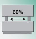
Figure 3: Generally, you should never apply full machine tonnage over an area that’s less than 60 percent of the distance between the side frames.
These formulas apply to air forming. If you’re bottoming or coining, you need to take this into account. Bottoming and coining tonnage calculations are rough approximations at best, because they can vary depending on the machine operator. But these bending methods do increase required tonnage substantially. If you’re bottoming, you need to multiply your calculated tonnage per inch by at least a factor of 5; if you’re coining, the factor can be 10 or even more.
Also note that the maximum tonnage doesn’t happen all at once; it builds along a steep curve. Under close observation, you will notice that 80 percent of the total tonnage is developed in the first 20 degrees of bend, so even a small bend angle can produce enormous pressures on the tooling and equipment.
There’s also more tonnage to consider than just what it takes to bend the sheet. Workpiece size also can affect tonnage requirements. When you are working with a small part, this force is extremely small. But for larger parts, the force can be significant. Supporting the material—be it with a lot of manpower, material lifters on the brake itself, or a crane—can help mitigate this effect.
Whether you are using a tonnage chart or calculating the tonnage requirements manually, you need to know how to apply the information. The job’s tonnage requirements should not exceed the tonnage capacity of the press brake or the tooling.
Press Brake Tonnage Capacity
Before continuing, we need to define some terms, the first being deflection. Deflection is the temporary deformation of the press brake’s ram and bed that occurs naturally under a load (see Figure 2). When the pressure is removed, so is the deflection present under load, and the ram and bed return to their original positions. In other words, deflection is normal and to be expected.
The second term is upset, which occurs when you exceed the maximum deflection of the press brake ram. When this happens, the ram and bed stay permanently deflected (bent); once upset, the press brake ram and the bed become difficult and expensive to repair.
Most press brakes are designed for centerline loading; that is, they are designed for work in the center of the press brake bed. The ram power comes from the cylinders on either side of the bed, while the force of the bend is in the center.
Deflection is not always present. On machines that allow off-center loading, you can work directly under a hydraulic cylinder and not have any deflection present, but you have only half the press brake tonnage available. Your limit then is either the tool’s load limit, or the hardness of the ram and its ability to resist the tonnage.
Exceeding the allowable tonnage for the press brake will cause ram upset. The load limit is machine-specific. Only the machine vendor can tell you the centerline load limit of your press brake; it may be 30-tons per foot or it may be 55 tons a foot. You need to research that information with the press brake manufacturer.
Generally speaking, you should never apply full machine tonnage over a bend length that’s less than 60 percent of the distance between the side frames (see Figure 3). If you have, say, a 10-ft.-long bed between the side frames, a full load can be applied uniformly to forming lengths of only 6 ft. or greater. This rule should be applied to most crowning systems as well. If you use full tonnage over less than 60 percent of the bed length, your brake will suffer some degree of upset in the bed and ram.
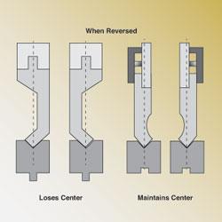
Figure 4: Standard American tooling (left) is reversible as far as pressure flow is concerned, but it can lose its center in the die. Note the small space that appears between the punch and right-hand die face. European-style tooling (on the right) is completely reversible as far as centers are concerned, but the pressure flow changes, as shown in Figure 5.
Say you have a 250-ton press brake with 14 ft. between the side frames. This means that at full load you have a minimum working area of 60 percent of the bed length (0.60 × 14), or 8.4 ft. You then divide 250 tons by 8.4 ft., giving you 29.76. After rounding up, the maximum tonnage per foot under load becomes 30 U.S. tons per foot. (When making your calculations, be sure that the units are consistent; 1 U.S. ton equals 1.102 metric tons.)
Punch Mounting Considerations
There are three styles of punches and three different punch mountings: American planed with dual shoulders; European-style precision-ground with a single shoulder; and the New Standard, which mounts directly onto the ram, and the pressure flows directly through the head of the tool and, in some cases, through the die shoulders.
Pay special attention to how the pressure flows through the tool when mounting the punch in the press brake. Standard American tooling is reversible as far as pressure flow is concerned, but reversing the punch can lose its center (see Figure 4), which can cause forming problems. (It also loses the relationship from the backgauge to the bend line, but that’s another topic altogether.)
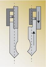
European-style tooling is reversible as far as centers are concerned, but they can be installed incorrectly. Notice the tooling setup on the right in Figure 5. The pressure flows past the ram and onto the mounting bolts. This creates a dangerous situation.
Tonnage Capacity of Tooling
For the most part, manufacturers publish a list of tooling they produce by the reference number and the allowable tonnage per foot each tool will handle. Dividing that tonnage value by 12 gives you the maximum allowable tonnage per inch for that tool. Multiply that value by the total inches of bend length, and you get the maximum allowable tonnage over that length of bend. Make sure this value exceeds the required tonnage value for the job at hand.
Over the years I have written many articles about how to develop the tonnage requirements for a particular situation, and I always follow the explanation with the statement, “Never exceed the manufacturer-specified maximum allowable tonnage,” only to be asked later, “My tooling isn’t rated, so how do I know if I’m using too much tonnage?”
It is true that some press brake tooling isn’t rated for tonnage; this is common with American planed tooling. Exactly how much tonnage per foot a given tool will withstand depends on the tool’s material, surface treatment, and geometry. Even for the most experienced engineers, this can be a difficult call.
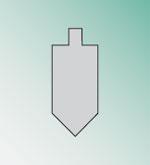
If a straight punch at least 2 in. wide does not have a tonnage rating, the tool’s load limit can be the centerline load limit of a typical press brake with a 30-ton-per-foot limit. This is because when you use a standard straight punch in which the body of the tool is at least 2 in. wide (see Figure 6), it is safe to say that it can withstand far more tonnage than 30 tons per foot. (Of course, this may not apply when using a press brake with higher load limits.)
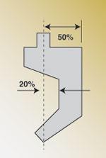
A gooseneck punch with a deep throat, designed for large return flanges, withstands significantly less tonnage per foot than a standard 2-in.-thick straight punch. The greater the gooseneck punch throat depth, the less its tonnage capacity (see Figure 7). For instance, a 70 percent (20 percent past center) throat depth produces a 30 percent drop in tonnage capacity from that of a straight tool, depending on the specific tool design.
Why Tonnage Data Is Critical
Ideally, you should refer to tonnage capacity information from both the toolmaker and press brake vendor. Having such data and fully utilizing it helps you avoid a potentially dangerous overtonnage situation.
Pushing a machine beyond its limits wreaks havoc on all fronts. An expensive press brake may be damaged beyond repair. Modern press brake tooling reaching 75 HRC can explode under extreme pressure. Worst of all, it puts the press brake technician in serious danger.
About the Author

About the Publication
subscribe now

The Fabricator is North America's leading magazine for the metal forming and fabricating industry. The magazine delivers the news, technical articles, and case histories that enable fabricators to do their jobs more efficiently. The Fabricator has served the industry since 1970.
start your free subscription- Stay connected from anywhere

Easily access valuable industry resources now with full access to the digital edition of The Fabricator.

Easily access valuable industry resources now with full access to the digital edition of The Welder.

Easily access valuable industry resources now with full access to the digital edition of The Tube and Pipe Journal.

Easily access valuable industry resources now with full access to the digital edition of The Fabricator en Español.
- Podcasting

In this episode of The Fabricator Podcast, Caleb Chamberlain, co-founder and CEO of OSH Cut, discusses his company’s...


