


Forming aluminum on the press brake: Bending soft, not sharp
Why air bending soft aluminum may call for a larger punch-nose radius
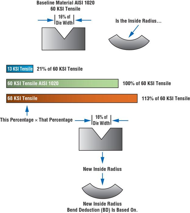
Figure 1
Using percentages and a material’s strength data, we can predict exactly what the
achieved inside bend radius will be.
Q: I came across a bending issue that has me completely baffled. I have a 0.984-in. die and a 0.03-in. (1-mm) punch. We were working with 0.125-in.-thick 6061-T6 aluminum, but we were experiencing cracking problems, so we switched to 1100-O aluminum, with a specified tensile strength of just 13,000 PSI. According to the 20 percent rule, I should be getting an inside bend radius of about 0.033 in. And yet our test bends give us an inside bend radius closer to 0.170 in. After working the math, I found that this value would make sense if the material had a 68,000-PSI tensile strength, but certainly not 13,000 PSI. What explains this difference?
That’s my dilemma. It’s not that we can’t just bend a test piece and get it right away. I just pride myself on being able to get it right before we ever cut a piece of material. Being able to calculate jobs accurately is especially helpful with parts that have multiple bends at various angles.
—Brent Hiatt, Challenge Tool & Mfg. Co., New Haven, Ind.
A: The reason for your discrepancy has to do with the bend turning sharp because of the narrow punch tip you’re using. The narrow punch tip also may have contributed to your cracking problems with the T-6 material.
As you are already aware, when air forming the inside radius is proportional to the die width by material type and tensile strength. This is true of all air forms, regardless of the die style you are using, be it a V, acute, or channel die. This is the essence of the 20 percent rule.
Remember that “20 percent” is only a title. Actual percentages change with material type and tensile strength. These values are just easy-to-use estimates for general sheet metal fabrication.
- 304 stainless steel: 20 to 22 percent of the die opening
- 60,000-PSI cold-rolled steel: 16 percent
- 5052 H32 aluminum: 12 to 14 percent
- Hot-rolled pickled and oiled: 14 to 16 percent
For this interpretation of the 20 percent rule, our baseline material is the 60-KSI cold-rolled steel (in bold); this is the value all other values are derived from. It’s also the simplest, most basic way of finding the inside radius of an air form, especially handy on the shop floor when basic information may not be available.
Calculating Precise Values
Judging by your question, you bring up an important point: The percentages in the 20 percent rule are based on the tensile strength of the material and not necessarily the material type, though for this discussion, at least, they are really the same thing (see Figure 1). Nonetheless, by applying our old friend Mr. Mathematics, we can achieve extreme accuracy with our calculations.
This is something I don’t discuss too often, because it’s a little deep in the weeds, and the general percentages for the 20 percent rule tend to work pretty well. Still, finding the exact percentage is mathematically pretty easy to do, especially considering you know the material tensile strength. If you come across material for which you can’t find the tensile data, you can find the required information after a quick Web search.
To obtain a specific percentage for a specific material, divide its tensile strength by 60,000 PSI, then multiply the result by 16 percent (the baseline material’s percentage of the 20 percent rule). Finally, multiply the result by your die opening:
20 Percent Rule Applied to Different Materials:
Material tensile in PSI/60,000 = Tensile difference factor
Tensile difference factor × 0.16 = Die width percentage
Die width percentage × Die width = Inside bend radius of an air form
By your question, you probably have already calculated the inside bend radius this way for both 68,000-PSI material and your 13,000-PSI soft aluminum:
20 Percent Rule Applied to 68-KSI Material:
68,000/60,000 = 1.13
1.13 × 0.16 = 0.181 (or 18.1 percent of die width)
0.181 × 0.984 = 0.178-in. inside bend radius
20 Percent Rule Applied to 13-KSI Aluminum:
13,000/60,000 = 0.216
0.216 × 0.16 = 0.034 (or 3.4 percent of die width)
0.034 × 0.984 = 0.033-in. inside bend radius
Sharp Bends in Soft Material
Once you access the material’s tensile strength data, you can predict exactly what the achieved inside bend radius will be. Using a tensile strength multiplier, as you have done, you will produce the most accurate bend allowances, setbacks, and bend deductions—usually. Still, you measured a 0.170-in. radius, almost 0.137 more than what you correctly calculated. Why the discrepancy?
It has to do with the concept of sharp bends. A sharp bend is the minimum inside bend radius you can achieve before the punch nose starts to form a crease along the bend line.
For a more in-depth discussion about sharp bends, see last month’s column. As described last month, the forming tonnage needs to be less than the punching tonnage. The punching tonnage is the force required for the punch tip to penetrate the material surface and start forming a crease along the bend line.
Here’s your forming tonnage:
Material factor = Tensile strength in PSI/60,000
Forming tonnage per foot =
{[575 × (Material thickness squared)]/
Die width} × Material factor
Material factor = 13,000/60,000 = 0.21
Forming tonnage per foot = [(575 × 0.015625)/0.984] × 0.21 = 1.917 tons per foot
To calculate the punching tonnage, we need the land area, or area of contact between your 0.03-in. punch and workpiece over 12 in. (1 ft.). To calculate the punching tonnage, we again incorporate a material factor for soft aluminum of 0.30.
Land area = Punch radius × 12
Punching tonnage = Land area ×
Material thickness × 25 × Material factor
Land area = 0.03 × 12 = 0.36
Punching tonnage in the land area =
0.36 × 0.125 × 25 × 0.30 = 0.337
So it takes 1.917 tons per foot to form, yet only 0.337 tons in the land area (1 ft. wide by 0.03 in. deep) for the punch to penetrate the material. Put another way, it takes 568 percent more tonnage to form this material than for the punch to break the surface and start to form a crease along the bend line. So what is the minimum sharp radius in this application? It turns out to be the following:
Land area = 0.172 × 12 = 2.064
Punching tonnage = 2.064 × 0.125 × 25 × 0.3 = 1.935
The math shows that the minimum punch radius you need to prevent creasing the bend for 13,000-PSI material is 0.172 in. This happens to be very close to the radius you measured. You may have expected the 0.033-in. inside radius, but short of forcing the radius into the part, the minimum achievable floated radius should be close to 0.172 in.
We have rules of thumb to guide us in precision bending, but exceptions abound. It’s generally true that the higher a material’s tensile strength value, the larger the floated inside radius. But in cases where you’re working with low-tensile-strength material, the minimum sharp radius is quite large.
The solution to achieving and maintaining the radius you planned is to ensure that the punch-nose radius is as close as possible to the radius you want to achieve. This in part is how aircraft tooling works, in which you have narrow die widths and yet relatively large inside bend radii.
Precise Calculation, Better Parts
It’s good to know you take pride in getting it right before test bending, even when working with multiple bends at various angles. Of course, if you change your bend angle, you also change your radius. Springback (bend angle versus bent angle) has its effect. Also, when you bend sheet metal in a die, you actually don’t form a perfect radius; instead, you actually form a parabola, an effect that becomes especially apparent on profound-radius bends, in which the radius is more than 10 times the material thickness.
Remember, all this relates only to air forming. In bottoming and coining, the inside radii are developed using a different set of values and processes—and they’re every bit as predictable as the inside radius calculations described here. In bottoming, the inside radius relaxes upon release for pressure, much the same way that springback relaxes when the load is released.
Different angles, the parabola effect, radii in bottoming and coining—it’s possible to calculate the inside bend radius in all these circumstances, and we’ll tackle all this and more in upcoming columns.
About the Author

About the Publication

subscribe now

The Fabricator is North America's leading magazine for the metal forming and fabricating industry. The magazine delivers the news, technical articles, and case histories that enable fabricators to do their jobs more efficiently. The Fabricator has served the industry since 1970.
start your free subscription- Stay connected from anywhere

Easily access valuable industry resources now with full access to the digital edition of The Fabricator.

Easily access valuable industry resources now with full access to the digital edition of The Welder.

Easily access valuable industry resources now with full access to the digital edition of The Tube and Pipe Journal.

Easily access valuable industry resources now with full access to the digital edition of The Fabricator en Español.
- Podcasting

In this episode of The Fabricator Podcast, Caleb Chamberlain, co-founder and CEO of OSH Cut, discusses his company’s...
- Trending Articles
1
AI, machine learning, and the future of metal fabrication

2
Employee ownership: The best way to ensure engagement

3
Dynamic Metal blossoms with each passing year

4
Steel industry reacts to Nucor’s new weekly published HRC price

5
Metal fabrication management: A guide for new supervisors
