


How air forming works
In one form or another, air forming always has been a part of the forming process on a press brake. This was true even when coining and bottom bending were the dominant methods of forming. Without the use of custom-made tools, all bends other than 90 degrees were by default air-formed, even if the process wasn't named as such.
Three-point Method
So what is air forming? How does it work? Air forming is a three-point method that uses the top two corners of the V die and the tip of the punch as the three points (see Figure 1).
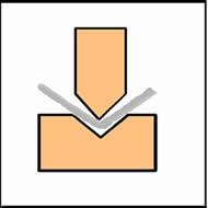 |
| Figure 1 |
Unlike bottom bending or coining, which reproduce the radius of the punch tip, air forming creates the inside radius as a percentage of the V-die opening, regardless of the punch radius.
The percentage varies by material type, producing an increasingly larger radius as the strength of the material increases; for example, 304 stainless carries a larger inside bend radius than mild cold-rolled steel.
Coining Versus Bottom Bending
While there is some confusion about the differences between bottom bending and coining, the biggest difference is the amount of tonnage required to produce the inside bend radius. Coining requires more tonnage than bottom bending.
Coining also requires that the punch tip be sharp (less than 63 percent of the material thickness) to produce a 90-degree bend—the sharper the better. It also requires that the material thickness neutral axis be penetrated, where thinning of the material is necessary.
Bottom bending re-creates the radius of the punch tip but does so without penetrating the neutral axis, and it does not require a sharp punch tip. Because of angular clearance between the punch and V-die faces (90-degree V die, 88-degree punch), bottom bending can reproduce bend radii up to three times that of the material thickness.
No Limitations With Air Forming
Air forming has no real limitations in terms of springback, tonnage, or material thickness and type. In fact, the tonnage required to air-form is substantially less than that required by bottom bending or coining.
The rule of thumb for press brake V-die selection has always been six to 12 times the material thickness, with eight times being the optimum width for lighter gauges of material and 10 times for heavier gauges. In the past it really didn't matter what the operator chose to use because coining and bottom bending were the only available methods and tonnage was the only factor that changed as the V-die width changed.
Note: The majority of bends created on a day-to-day basis are 90 degrees of the bend angle.
20 Percent Rule
As stated previously, when air forming, the inside radius is produced as a percentage of the V-die opening. Using the six and 12 times the material thickness rule will reveal a substantial difference in the inside radius that can be expressed by material type as follows:
- V-die width x 0.2 (20 percent) = Inside radius in 304 stainless steel
- V-die width x 0.15 (15 percent) = Inside radius in mild cold-rolled steel
- V-die width x 0.15 (15 percent) = Inside radius in H32 aluminum
- V-die width x 0.12 (12 percent) = Inside radius in hot-rolled steelFor example, for 0.046-in. cold-rolled steel:
- 6 x V-die opening = 0.276 in.
- 0.276 in. x 0.15 in. = 0.041-in. inside radius
-
- 8 x V-die opening = 0.386 in.
- 0.386 in. x 0.15 in. = 0.055 in.-inside radius
-
- 12 x V-die opening = 0.552 in.
- 0.552 in. x 0.15 in. = 0.082-in. inside radius
Try using some examples from your own shop to see just how accurate these methods and calculations really are.
Calculating the Desired Inside Radius
If you change the inside radius, you change the bend deduction (BD). This fact must be taken into account regardless of the method used to select your V-die opening. If you are looking for a specific inside radius, you can use the following formula to develop the correct V-die opening to achieve that result.
(Outside radius x 0.7071) x factor
- Factors:
-
- Material thickness < 0.125 in.
- Sharp = 4 in., Radius = 4.85 in.
- Material thickness 0.125 in. to 0.250 in.
- Sharp = 5 in., Radius = 5.85 in.
- Material thickness 0.250 in. to 0.375 in.
- Sharp = 6 in., Radius = 6.85 in.
Selecting the Punch Radius
Punch radius makes little difference in the final product because of the three points of air forming. The one exception is the sharp bend.
Using excessive tonnage, coining works by hitting the material with enough force to actually thin it, thereby relieving the natural springback of the material by ruining the metal’s integrity. Coining also works only with a sharp punch, rarely with a punch carrying a radius greater than 63 percent of the material thickness.
Bottom bending also works with a sharp punch bend radius. But a sharp punch radius in air forming only creates problems, which is probably the main reason some shops and operators fail to make the transition from coining and bottom bending to air forming.
A sharp bend is defined as any tool radius less than 63 percent of the material thickness. When a sharp relationship is used in an air forming operation, every change in material thickness, natural grain direction, material hardness, and so forth, will cause variations in bend angle and, therefore, variations in dimensions. Even though the punch radius is never accurately reproduced in the material during an air form, a ditch equal to the punch radius is set into the inside center of the bend radius.
For air forming it is always recommended that the punch radius be equal to or greater than the point where the material turns sharp—63 percent.
Note: Sharp bends are a function of the material and not the punch tip.
For air forming it is always recommended that the punch radius be equal to or greater than the point where the material turns sharp—63 percent.
In cases in which there is a one-to-one relationship between the material thickness and the inside radius, the eight times material thickness rule of thumb matches the calculated V-die opening exactly.
Die Angles and Springback
Originally, all V dies were produced at 90 degrees standard and acute V dies at 45 degrees and 30 degrees. These configurations were sufficient when bottom bending and coining were the preferred methods for press brake bending.
When air forming became the predominant method of bending, it was necessary for die angles to change to help compensate for springback. No longer was tonnage alone sufficient to alleviate springback.
When the included angle of the V die is changed, the sides of the die help to push the material farther around the punch tip, thereby compensating for some of the inherent springback.
V-die angles do change at regular intervals and may vary slightly from manufacturer to manufacturer for each group. Some overlap occurs at the division points.
The V dies listed below are standard off-the-shelf, precision-ground dies, but they can be ordered with any angle.
- 0.157 in. to 0.472 in. = 90 degrees
- 0.472 in. to 0.980 in. = 88 degrees
- 0.980 in. to 1.472 in. = 85 degrees
- 1.472 in. to 1.980 in. = 78 degrees
- 1.980 in. to 2.472 in. = 73 degrees
As the material thickness increases or as the inside radius increases in relation to the material thickness, a corresponding increase in springback occurs. This increase is at least partially compensated for with smaller included V-die angles that help push the material just a little bit farther around the punch tip, assuming there is sufficient angular clearance in that tool (see Figure 2).
 |
| Figure 2 |
Caution is needed to ensure that you don't mismatch punch and V-die angle, for example, by using a punch with a 90-degree angle in a V die at 88 degrees. Doing so can break a tool, or at the very least, produce a very ugly bend. The die angle always should be equal to or greater than the complementary angle of the punch.
The die angle always should be equal to or greater than the complementary angle of the punch.
Even though there still are plenty of naysayers when it comes to air forming, correctly done, the technique can be every bit as accurate as bottom bending or coining, without the excessive tonnage. All that's required is careful attention to selecting the right tools.
About the Author

About the Publication

subscribe now

The Fabricator is North America's leading magazine for the metal forming and fabricating industry. The magazine delivers the news, technical articles, and case histories that enable fabricators to do their jobs more efficiently. The Fabricator has served the industry since 1970.
start your free subscription- Stay connected from anywhere

Easily access valuable industry resources now with full access to the digital edition of The Fabricator.

Easily access valuable industry resources now with full access to the digital edition of The Welder.

Easily access valuable industry resources now with full access to the digital edition of The Tube and Pipe Journal.

Easily access valuable industry resources now with full access to the digital edition of The Fabricator en Español.
- Podcasting

In this episode of The Fabricator Podcast, Caleb Chamberlain, co-founder and CEO of OSH Cut, discusses his company’s...
- Trending Articles
1
AI, machine learning, and the future of metal fabrication

2
Employee ownership: The best way to ensure engagement

3
Dynamic Metal blossoms with each passing year

4
Steel industry reacts to Nucor’s new weekly published HRC price

5
Metal fabrication management: A guide for new supervisors
