


Contributing Writer
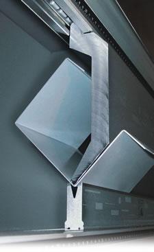 |
| Tall gooseneck punches can bend deep parts and parts with complicated bend sequences. |
In recent years faster, more efficient cutting and blanking methods have emerged. However, these cutting efficiencies and corresponding increases in productivity have not always been met with similar increases in press brake productivity. Consequently, this has created a need to find new ways to improve press brake process productivity.
Once a press brake has been installed, methods to improve its functionality to increase bending capacity may be limited; therefore, you might consider purchasing more press brakes, but that will require more floor space and more operators. An alternative for improving press brake productivity and eliminating the bottleneck may be with more advanced tooling, antideflection (crowning) systems, and clamping systems.
In the past when bottom bending and coining were the only options, it was common for press brake owners to accumulate large inventories of press brake tooling. However, the advent of CNC press brakes, precision-ground segmented tooling, and precision air bending has made it possible to form more materials and part configurations with fewer tools.
The two most versatile punch types for air bending applications are acute-angle punches and gooseneck punches (see introductory image).
Gooseneck punches allow you to form deep channels, boxes, and other parts with long return flanges. Gooseneck punches with a tip angle of 88 degrees or less can help you deal effectively with springback.
Acute-angle punches allow you to bend almost any angle. They can be used to create the acute bend required for hemming applications.
When produced from high-strength alloy steel and properly heat-treated, both punch styles are fairly strong and bend a range of material types and thicknesses. Generally, the taller a punch is, the more versatile it is. The flexibility these two punch styles provide normally results in fewer punch changes. Consequently, less time is needed for setup, and productivity will increase.
Although the angle of the V opening on the die must match the angle of the punch tip in bottom bending and coining operations, this is not necessary with air bending, because the final bend angle is determined by the penetration of the punch into the die. For example, you can use acute-angle punches with a 28-degree tip and gooseneck punches with an 86-degree tip with dies with 30-degree V openings.
This can reduce the total number of dies required to bend 0.036- to 0.135-inch (1.0- to 3.5-mm) mild steel, aluminum, and stainless steel. Be sure to use extra caution to avoid overpenetrating the die and possibly damaging it when using a die that has a V opening with an included angle that is less than that of the punch tip.
When selecting a die, consider its overall working height. Tall dies are flexible and allow you to bend parts with long down flanges (see Figure 1). Short dies normally are less expensive and consume less open height.
Because single-V dies are narrower than the 2-V dies common with most European-style tooling systems, they are less likely to interfere with parts with a complicated bend sequence.
In addition, single-V dies normally are designed with a common tang, so that a full range of dies can be used in a single die holder or antideflection device (crowning system). This reduces setup time because it eliminates the need to utilize multiple die holders to accommodate multiple die designs.
Durability. Tooling durability is an important consideration. Many tooling manufacturers now offer surface hardening on standard press brake tooling. These hardening processes include CNC deep hardening, laser hardening, induction hardening, and coating. All processes provide good wear resistance compared to tools with unhardened wear surfaces. For example, research has shown that tools that have been CNC deep-hardened will last seven to nine times longer than tooling with unhardened surfaces.
Portability. Finally, a good press brake tooling system should be portable. It should be supported by a series of holders for the upper and lower beam (ram and bed) that allow you to move it from one press brake to another.
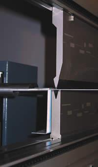 |
| Figure 1 Tall dies can bend parts with long down flanges. |
The advent of high-precision, quick-change press brake tooling systems has resulted in huge productivity gains. However, it is quite common for precision-ground punches to be used directly against the upper beam of the press brake and to be held in place by the manual ram clamps originally provided with the machine. On many press brakes, the load-bearing surfaces of the upper and lower beam are milled to finish rather than precision-ground. Inconsistencies in these surfaces directly alter the quality of the finished parts. This type of installation also does not speed up the loading and unloading of tooling.
Advancements in clamping system technology in recent years have been driven by reduced lot sizes and an increase in the number of setups that press brake operators must perform. Fortunately, you have many clamping systems to select from, including manual clamping systems that simply open and close the clamps quickly and hydraulically driven systems that clamp, seat, center, and align all of the tooling with the push of a single button (see Figure 2).
Precision clamping systems also provide a high-precision, load-bearing surface for punches, thereby reducing the problems with inconsistent bend angles caused by poorly machined surfaces or moderately damaged surfaces on the upper beam. They also act as an insulator against damage to the upper beam of the press brake.
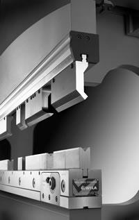 |
| Figure 2 This hydraulic clamping system for North American-style press brakes is equipped with a crowning system that uses opposing wave tecnology to compensate for machine deflection. |
Finally, many advanced clamping systems enable you to clamp punches either with the relief area facing toward the rear of the machine or facing toward you. This provides additional versatility because part extraction often is easier and less cumbersome when the punch is loaded with the relief area facing toward you.
If your press brake is 8 feet long or longer, unless you bend nothing but thin materials or are fortunate enough to have a press brake with built-in deflection compensation, you probably have been shimming dies to overcome machine deflection. The time consumed and the subsequent costs of this tedious and productivity-robbing process are often overlooked.
Antideflection (crowning) systems are available that eliminate this problem. Basic systems are manually adjusted, and set screws clamp lower dies in place. Others are equipped with more advanced clamping bars that can be tightened against the die manually or with hydraulics for ultrafast die changes. Clamping bars make it possible for you to position small die segments anywhere along the full length of the unit to achieve equal clamping pressure. This prevents them from being moved or knocked over while handling the material.
The deflection-compensating components in these systems can be a simple set of opposing wedges or a set of highly advanced opposing waves. Depending on the design, the motion of the wedges or opposing waves against each other cause the unit to deflect in an upward motion to compensate for the amount of deflection that is being generated in the press brake when it comes under load. You can adjust these units with a basic lever, a hand crank at the end of the unit, or with an electronic motor driven by the CNC on the press brake.
Some of the more advanced antideflection systems available also feature localized adjustments. This enables you to increase or decrease the amount of deflection compensation at frequent intervals along the full length of the unit. This makes it possible to fine-tune the deflection-compensating curve of the unit to overcome the nuances built into the machine, as well as compensate for wear that is specific to a particular area of the upper and lower beam or a specific punch or die.
In the end, the choice of which crowning unit is best for you should rest solely on which features and benefits best suit your needs. Whichever system you choose can eliminate shimming with a process that requires only a matter of seconds to complete.
Ironically, a press brake never comes into contact with the material that it bends; only the tooling and backgauge do that. When considering ways to improve press brake productivity, it is imperative that you examine all of the elements that affect overall productivity. This includes the machine, control, operating software, and everything that goes between the upper and lower beams—the tooling system, clamping system, and deflection-compensating device. Fortunately, when it comes to advanced tooling systems, clamping systems, and antideflection systems, the choices have never been better.
David Bishop is a business development manager, Wila USA, 9135 Guilford Road, Columbia, MD 21046, 301-490-9652, fax 301-490-3991, dbishop@wilausa.com, www.wilausa.com.

The Fabricator is North America's leading magazine for the metal forming and fabricating industry. The magazine delivers the news, technical articles, and case histories that enable fabricators to do their jobs more efficiently. The Fabricator has served the industry since 1970.
start your free subscription
Easily access valuable industry resources now with full access to the digital edition of The Fabricator.

Easily access valuable industry resources now with full access to the digital edition of The Welder.

Easily access valuable industry resources now with full access to the digital edition of The Tube and Pipe Journal.

Easily access valuable industry resources now with full access to the digital edition of The Fabricator en Español.
In this episode of The Fabricator Podcast, Caleb Chamberlain, co-founder and CEO of OSH Cut, discusses his company’s...


