M.Asc.
The contact tip is one of the smallest and relatively inexpensive components in a gas metal arc welding (GMAW) system, but it can cause catastrophic failure and production downtime, highly penalizing productivity.
The basic function of the contact tip is to transfer welding current to the consumable wire as it passes through its center bore and makes electrical contact with the bore surface.
Good electrical contact and easy feedability are key factors in contact tip performance; bore conditions must facilitate feedability while providing sufficient electrical contact. Consequently, for many years copper has been the material of choice, not only because it displays the second-best electrical conductivity among metals, but also because it's readily available.
GMAW process stability is sensitive to small changes in conditions at the contact tip. In addition to predefined maintenance schedules, poor weld quality and process instabilities usually trigger contact tip replacement. However, the root causes of most process failures are more complex.
 |
| Figure 1 In this schematic of a GMAW electrical circuit, the welding voltage, V, as measured at the power source terminals, isn't the true arc voltage but the sum of a number of voltages along the welding circuit. The most significant contributors to the overall potential are the arc voltage itself, Varc, and the wire extension voltage, Vext. The latter is the somewhat steady part of the welding wire that sticks out of the contact tip before the wire melts. |
Process failures associated with contact tips are numerous, but they generally can be classified into two main groups:
1. Those that result in some type of arc failure, such as burnback, bad starts, or arc instability.
2. Those that result in erroneous weld deposition in robotic welding.
Arc Failures. Burnback, bad starts, and other similar faults are, by far, the most common causes of downtime and result in lost productivity. These arc failures occur when factors that maintain steady arc burning are unbalanced (see Figure 1).
For a given set of power supply conditions, the welding current is determined by factors such as the wire feed rate, electrode diameter, electrode chemistry, contact-tip-to-work distance, and shielding gas composition. The melting rate of the wire is determined by the wire extension and welding current. The welding current is determined by the wire feed rate. The dynamic balance between the wire feed rate and the melting rate results in steady metal transfer with globular, spray, or short-circuiting metal transfer characteristics, depending on the welding conditions. This delicate balance can be upset by small variations in the wire feed rate and the wire extension, or during transient conditions such as the starts or ends of welds (or of pulses in pulse GMAW).
Feed rate instability is common and typically originates with anything along the wire path that opposes the steady supply of consumable wire. If at any time the feed rate overwhelms the melting rate, then stubbing can occur. However, if the melting rate surpasses the feeding rate, burnback can occur.
 |
| Figure 2 Tin-zinc coatings on steel liners can improve steel wire feedability. |
Examples of causes for instability are as follows:
A welding wire that is too stiff can cause excessive friction along the path, while a wire that is too soft can tangle inside the torch. Dirty, rough, or scaly wire surfaces are likely to release debris inside the bore, which eventually causes clogging of the contact tip bore. In particular, the natural expansion and contraction of contact tips during repetitive welding cycles can induce faulty weld starts as the bore becomes clogged with debris.
Drive rolls with the wrong profile or that aren't properly adjusted can cause wire slippage, excessive wire deformation, or metal debris that accumulates in the contact tip.
Liners that haven't been specified or installed properly can cause feedability problems. Anything from internal liner diameter to the type of coating (see Figure 2) to the cutting method and length affect the feedability performance of these components.
Excessive torch length and excessive cable looping can cause unnecessary friction, which can result in feeding problems.
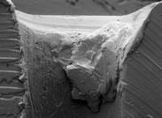 |
| Figure 3 This scanning electron micrograph shows microspatter buildup inside the contact tip bore. |
Contact tips with smaller bore diameters can generate additional friction, especially when the bore surface is rough. Excessive spatter accumulation can cause undesirable bridging of the wire or microspatter buildup inside the tip cavity (see Figure 3).
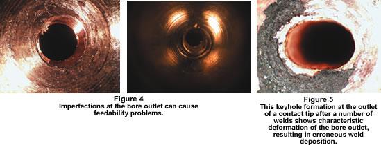
Spatter accumulation is promoted by high surface temperature and rough surfaces. The use of copper alloys, which have lower thermal conductivity than pure copper, can cause excessive spatter accumulation, which increases the chances of burnback in applications that call for multiple short welds. Contact tips that contain sharp edges near the front end are more prone to excessive spatter accumulation. The same applies to contact tips that contain metal debris or imperfections near or inside the bore (see Figure 4).
Variability of the last point of electrical contact is another source of arc instability. The last point of contact moves along inside the tip bore in response to numerous factors, including resistivity changes along the bore, wire cast and helix, tolerance inconsistency, and variation of the distance to the workpiece.
 |
Selecting the proper dimensional match between the wire cast and bore size is important. The cast of the consumable wire mainly is determined by the size of the supply reel, drive roll tension, and gooseneck angle. A tight-cast wire works better with large tip bores since the wire always exerts pressure on the internal surfaces of the bore. A straight wire requires tighter bore diameters to ensure sound and stable electrical contact. The latter, however, may require an exceptionally clean and consistent wire surface to prevent jamming of the contact tip.
Transient power conditions occurring during arc starts, crater, pulsing, or short-circuiting can lead to burnback failures. High current surges at the start of the weld in combination with a slow run-in may cause burnback. High current spikes at the beginning or the end of pulses in pulse mode also can produce arc failures. Similar phenomena are likely to occur at the end of the welds.
Fortunately, you can adjust these transient conditions in inverter power supplies, which allow user intervention. Power supplies with predefined or fixed pulse waveforms may be more difficult to adjust, but most equipment manufacturers can provide technical support.
Erroneous weld deposition in robotic welding can cause costly robot program readjustments. In robotic welding, the tip of the wire often is used as a positioning reference or tool-center point (TCP). The stable position of the wire stick-out over a large number of welds is most desirable.
A robotic workcell has multiple sources of positioning variability, including positioners, fixtures, tooling, parts, and the manipulator, all of which can affect TCP repeatability. Tip bore wear also contributes to TCP variability in robotic welding because of the continuous rubbing by the moving wire inside the tip bore at elevated temperatures, which eventually wears off the bore outlet (see Figure 5). For sheet metal welding, excessive bore wear can result either in lack of fusion or burn-through weld defects.
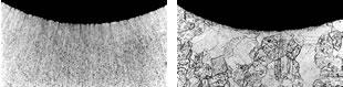 |
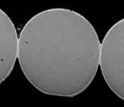
| Figure 6 Grain growth and recrystallization phenomena near the bore surface result from multiple exposures to elevated temperatures during welding. On the left is a new contact tip before welding, and on the right is coarse grain structure developed after welding. |
It's not clear what the exact microscopic mechanisms that produce wear in contact tips are. Some studies have suggested that a relatively small region at the bore outlet sustains most of the damage. At this region, current densities and temperatures are high enough to promote electrical erosion, abrasion, and oxidation phenomena. Whatever the mechanism may be, the wear rate is closely related to the service temperature as well as to the properties of the tip material.
The service temperature indicates the average amount of heat that accumulates in the tip, which roughly corresponds to the difference between 10 and 20 percent of the welding power minus the amount of heat dissipated into the torch and surroundings. Experimental measurements have revealed that contact tip operating temperatures at the front could be in excess of 500 degrees C. Exposure to such temperatures triggers microstructural changes that deter the original mechanical properties of contact tips (see Figure 6 and 7).
From a materials standpoint, pure copper may be relatively soft to withstand abrasive wear at elevated temperatures. Normally, contact tip material gets fabricated through sequences of cold drawing steps that work-harden copper. However, for many applications this may not be sufficient, and quite often manufacturers specify copper alloys containing chromium, zirconium, or beryllium, which display better mechanical properties.
While these alloys may provide better wear resistance in certain applications, their electrical and thermal properties are below those of pure copper. This may result in arc instability, leading to frequent burnback failures. Also, low thermal conductivity promotes higher tip temperatures, which attract more spatter.
A trend in recent years has been to use alternative copper-based materials, which preserve the high electrical conductivity of pure copper while providing suitable mechanical properties. One example is powder metal copper composite materials that take advantage of dispersion strengthening.
 |
| Figure 7 Temperature can affect the conductivity of selected metals and alloys. Among these changes, higher service temperature translates into lower electrical conductivity. |
Because of the high number of unforeseen variables in the GMAW process, it's impossible to define one set of guidelines that addresses all contact tip life issues in all possible situations. The following guidelines, however, can help you extend the life of your contact tips:
1. Keep the wire feed rate stable.
Maintain the wire surface by placing cleaning pads on the wire before the feeder inlet. While adding certain lubricants has been claimed to reduce burnback, petroleum-based fluids are likely to form carbon residues that may clog the contact tip and defeat the purpose.
Use dust covers or protective liners wherever the wire is exposed to the plant environment.
For steel wire, specify copper-plated wire.
Correctly specify the torch liner's geometrical and dimensional characteristics and the preferred type of coating. Tin-zinc coatings appear to work well for steel welding, while PTFE thermoplastics go well with aluminum wire.
Follow the manufacturer's specifications when adjusting your drive roll and dereeler mechanisms.
Use the minimum torch cable length possible, and avoid excessive torch looping.
2. Maintain a low temperature.
Avoid using contact tips that display sharp features or intricacies at the front, such as flats. These increase the chances for spatter and heat buildup. Ensure that contact tip bores are free of metal debris, residues, or imperfections from manufacturing.
Apply antispatter fluid to minimize spatter accumulation.
Avoid using contact tips with tapered front geometry because a narrower front end will tend to overheat more quickly, reducing the useful life of the tip.
Use water cooling wherever air cooling may appear insufficient. This typically is the case for welding currents higher than 500 amps. However, beware that water cooling can bring along mechanical complexities that affect the cost of acquisition, installation, operation, and maintenance of the welding system.
Minimize spatter generation by using inverter power supplies that allow dynamic control of the current waveform. This is particularly useful for sheet metal welding using short-circuiting metal transfer mode.
3. Ensure that undesirable spikes during arc start, crater, pulse, and short-arc transients aren't present in the power supply current waveform.
4. Keep the last point of electrical contact stable.
Adequately match the internal diameter of the contact tip to the wire diameter. When using wire with tight cast, specify contact tips with loose tolerance and vice versa.
Use copper-coated steel wire.
5. Use contact tips made of materials that display high electrical conductivity while providing high wear resistance.
Dr. Julio Villafuerte is the corporate product development manager at Centerline Windsor Ltd., 415 Morton Drive, Windsor, ON N9J 3T8, 519-734-8464, fax 519-734-2024, JVillafuerte@cntrline.com, www.cntrline.com.
G. Adam, T.A. Siewert, T.P. Quinn, and D.P. Vigliotti, "Contact Tube Temperature during GMAW," Welding Journal, Vol. 80 (2001), p. 37.
C.J. Allum and L. Quintino, "Control of Fusion Characteristics in Pulsed Current GMA," IIW Doc. 212-582-84.
E.A. Brandes and G.B. Brook, Smithells Metals Reference Book, 7th ed. (Burlington, Mass.: Butterworth-Heinemann, 1992), pp. 19-1.
V.G. Degtyarev, M.P. Novikov, and N.M. Voropai, Paton Welding Journal, Vol. 3, No. 4 (1991), pp. 290-294.
E. Halmoy, "Electrode Wire Heating in Terms of Welding Parameters," The Physics of Welding, ed. J.F. Lancaster (Oxford: Pergamon Press, 1986), pp. 330-336.
R. Noch and J. Phillips, "Successful System Integration and Installation," in proceedings from the Robotic Arc Welding Conference, sponsored by the American Welding Society, Orlando, Fla., March 15-16, 1999.
H. Thier, H. Polrolniczak, and S. Schreiber, Schweissen und Schneiden, Vol.47, No. 5, May 1995, pp. 356, 358, 360-362, 365 (English translation of text and captions pp. E88-E90).
J. Villafuerte, "Dispersion Strengthened Copper for Heavy Duty Torch Tips and Electrode Caps," Welding Journal, Vol. 82, No. 11 (2003).
T. Yamada, O. Takana, "Fluctuation of the Wire Feed Rate in Gas Metal Arc Welding", Welding Journal, Vol. 66, No. 9 (1987), pp. 35-42.

The Welder, formerly known as Practical Welding Today, is a showcase of the real people who make the products we use and work with every day. This magazine has served the welding community in North America well for more than 20 years.
start your free subscription
Easily access valuable industry resources now with full access to the digital edition of The Fabricator.

Easily access valuable industry resources now with full access to the digital edition of The Welder.

Easily access valuable industry resources now with full access to the digital edition of The Tube and Pipe Journal.

Easily access valuable industry resources now with full access to the digital edition of The Fabricator en Español.
In this episode of The Fabricator Podcast, Caleb Chamberlain, co-founder and CEO of OSH Cut, discusses his company’s...