


Corrosion-resistant fabrication project enhances nuclear power station’s cooling system
Grate structure keeps marine life out of harm’s way
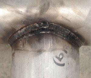
A pipe joint made from Rolled Alloys’ ZERON 100 pipe and ESAB’s Shield-Bright® 2594 flux-cored filler metal provides the properties needed to withstand immersion in the Pacific Ocean—the stresses of continuous wave action and the caustic properties of seawater. Photo courtesy of ESAB Welding & Cutting Products, Florence, S.C.
From its introduction in 1957 when it contributed 9.7 million kilowatt-hours (kWh) to the U.S. electricity supply, nuclear power has become a substantial player in electricity generation. By 1990 nuclear power was responsible for 577 million kWh of electricity, nearly 20 percent of the total. It has remained a key contributor, providing about 20 percent of the electricity supply ever since. This power comes from 104 reactors at 65 sites. Most are located in the eastern half of the U.S., with a handful in the western half.
The capital costs involved in building a nuclear-powered generating station are substantially higher than any other sort of power plant, which can be a boon to the contractors that put up the buildings, build the generators and reactors, supply countless valves and switches and gauges and control panels, plumb the systems that move the water, and wire together everything that runs on electricity. The build cycle takes years and provides countless opportunities to the businesses involved in the industry.
Depending on the locality, the plant’s environmental impact, and the sensibilities of the local community, a nuclear plant might need a custom-made component, something unique in the industry. Southern California Edison (SCE), which has a 75 percent stake in the San Onofre Nuclear Generating Station (SONGS), found itself in this position. Nuclear plants use quite a bit of water, and SCE learned that the intake units at SONGS developed enough suction to pull in an occasional seal, whale, or shark.
It needed a solution, some sort of big grate, one strong enough to stand up to the constant pounding of the waves in the Pacific Ocean and one corrosion-resistant enough to resist the caustic properties of saltwater. Also, it had to be large enough to disperse the suction power over a large area—otherwise, the suction would kill the animals by trapping them against the grate, while simultaneously stopping, or greatly reducing, the flow of water into the cooling system.
Armed with a design, SEC solicited bids for two such devices, formally called a loed. Vaguely resembling a birdcage, each loed is an enormous octagonal structure that measures 22 feet in height and 65 ft. in width (across the flats).
Loeded for Bear
The staff at Dimic Steel Tech felt that the company was up to the task. Founded in 1973 by Miles Dimic, a sheet metal mechanic from Yugoslavia, the Upland, Calif., company had decades of fabricating experience under its belt.
Initially involved in forming sheet metal, the company expanded into other areas—first plate, then tube and pipe. Capabilities include plasma cutting, punching, shearing, sawing, rolling, milling, machining, and welding. It embraced CNC equipment, added machining to its repertoire, and invested in laser cutters when the process emerged as a viable way to cut metal.
Now under the stewardship of Dimic’s daughter, Ana, the woman-owned business serves customers in the transportation, food processing, construction, recreation, HVAC, and commercial display industries. It also does some work in high-tech areas, such as making molecular-level microscopes used for nanotechnology and components used in the renewable energy field.
The company didn’t have much experience with welding the material specified for the loeds, ZERON® 100, a superduplex alloy manufactured by Rolled Alloys. Despite this small handicap, Dimic’s staff took a risk and bid on the project, largely relying on the experience and skills of veteran fitter/welders Rick Spencer and Steve Wangeman. Together they have more than 30 welding certifications on processes as varied as AC/DC gas tungsten arc welding (GTAW), gas metal arc welding (GMAW), flux-cored arc welding (FCAW), and shielded metal arc welding (SMAW).
Strong and corrosion-resistant, the alloy has a minimum yield strength of 80,000 pounds per square inch (PSI). The main alloying elements are chromium (25 percent), nickel (7 percent), and molybdenum (3.5 percent); the rest is made up of small amounts of copper, tungsten, carbon, nitrogen, manganese, silicon, phosphorus, sulfur, and iron.
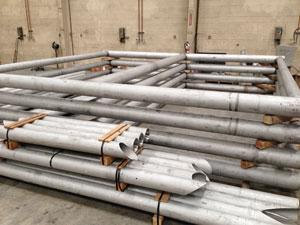
Figure 1: Dimic used more than its welding expertise to create the loeds. It used its laser cutting machine to cut the pipe for the outriggers to support the loeds and brace them to the ocean floor (front). At the rear are four half-frames which will make two 20- by 40-ft. frames.
Using the pitting resistance equivalent number (PREN) formula as defined by ASTM G48, (PREN = 1 x Cr% + 3.3 x Mo% + 16 x N%), the alloy has a PREN value of 1 x 25 + 3.3 x 3.5 + 16 x 0.25 = 40.55. A PREN higher than 32 is considered resistant to seawater.
Building the Structure
The framework of each loed is made from pipe; attached to the framework are grates made from lengths of ½-in.-thick steel.
“The bars are made out of ½-in. plate that we cut into long strips, which we used to build the grate sections. The framework is made from 8-, 6-, and 5-in. pipe,” said General Manager Mark Riker. See Figure 1.“Some of the panels have weak links, links that are meant to break if they encounter excessive loading, caused by a large amount of kelp or any other type of debris that would starve the cooling system of water,” Riker said. “They’re hinged on the bottom and have weak links at the top, so they break open, allowing water to flow freely.”
Logistics and Efficiency. Making a single weld usually doesn’t pose a big challenge, but making thousands of welds efficiently usually does.
“We did quite a bit of engineering work at our end,” Riker said, to overcome several challenges associated with the large number of welds and moving these large, heavy components.
Making the entire weld without moving the grate unit would require quite a bit of out-of-position welding, which really isn’t practical on a project of this scale. Likewise, flipping each unit over to prevent overhead welding would be a challenge because of each unit’s weight and size. When assembled, each grate would weigh thousands of pounds, and the width would make them unwieldy. Also, the shop’s overhead cranes left little leeway for flipping them over. The units would be even harder to handle when completed. Each 20- by 21-ft. section was really just half a grate, and had to be joined to another for a final size of 20 by 42 ft. Getting them out of the building was a head-scratcher because the door height is 15 ft.
Ultimately, Dimic put together a material handling system to flip each panel and several carts, designed and built in-house, to move them around the shop. It also leveraged other, unrelated fabrication experience to make the assembly process go like clockwork.
“We used our laser experience to build modular, interlocking fixtures, allowing the welders to set the lengths of material in place, one piece after another, and weld, one weld after another, until each 20- by-21-ft. grate section was complete,” Riker said. “We used these fixtures to build every section as rapidly as possible.”
Welding It All Together. Despite all of these big-picture, strategic considerations, making the units efficiently boiled down to welding processes and consumables.
Two of the job requirements helped Dimic home in on the welding processes to be used: First, the contract required complete joint penetration for every weld, and second, it prohibited short-circuit transfer, one of four recognized transfer modes of GMAW. The short-circuit process leaves some weld spatter behind, but more importantly, it doesn’t provide as much joint penetration as some other welding processes, said Jordan Maxwell, the company’s certified welding inspector. It also has a greater likelihood to introduce fusion-type defects, he said.
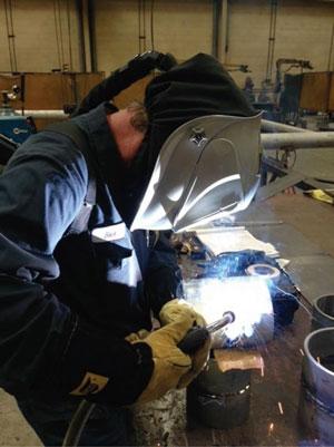
Figure 2: One of Dimic’s veteran fitter/welders, Rick Spencer, tests a welding procedure in the 5G position. On all of the 5G welds, including the GTAW root passes, Spencer and fellow welder Steve Wangeman welded vertical-up. “That’s the best way to get as much heat in the weld zone as possible,” said certified welding inspector Jordan Maxwell.
Therefore, the possibilities were pulsed-spray GMAW (GMAW-P), GTAW, gas-shielded FCAW (FCAW-G), and SMAW (also known as stick welding).
Dimic did a little research and found that Rolled Alloys makes a ZERON 100X filler metal for GTAW, which Dimic used for the complete joint penetration root passes. Welding superduplex material can be tricky, but this filler metal made the root passes go smoothly.
“The ZERON wire is amazing—it’s incredibly buttery,” Maxwell said.
For welds made in the flat position, Dimic chose another ZERON product from Rolled Alloys, a filler metal used for GMAW-P.
So far, so good, but this accounted for only about 10 percent of the welds for this project.
For the other 90 percent of the welds, which would be fixed vertical pipe welds (the 5G position), Dimic shopped around and found a couple of flux-core filler metals for superduplex applications. Pulsed-spray transfer works well for flat and horizontal welds, but it isn’t as effective for the 5G position with its vertical portions (see Figure 2).
After some welding trials, Dimic found that Shield-Bright® 2594, made by ESAB, provided good results. A close match for ZERON 100, the consumable is nearly identical in chemistry but has quite a bit more strength. The main constituents in the alloy are 25 percent Cr, 7 percent Ni, 3 percent Mo, and 0.25 percent N; the consumable’s corresponding chemistry is 25 percent Cr, 9 percent Ni, 4 percent Mo, and 0.25 percent N. When welded with 75 percent argon and 25 percent CO2, the consumable exhibits 100,000-PSI yield strength, according to the manufacturer, which is 20,000 PSI more than the base metal.
“It took us a while to dial it in, but when we did, it gave us the tilled edge I was looking for,” Maxwell said. “I was looking for a smooth-blending wire, and this wire hit it right off the bat.”
The initial results were good, but the weld characteristics weren’t quite optimized. The Dimic staff worked with ESAB’s local territory manager, Grant Melton, and an applications engineer, Jerry Mathison, to refine the process. Mathison determined that the initial settings were a little too hot, and recommended backing off the voltage and the wire feed speed. They made some other subtle changes, too. For example, the manufacturer recommends an interpass temperature of ±200 degrees F, but Dimic held it even tighter to ±150 degrees F and got better results in both slag removal and the visual appearance of the weld, according to Maxwell.
In addition to testing the welds for the necessary mechanical properties and corrosion resistance per ASTM G48, the consumable had to pass another test, a subjective evaluation: Were the welders comfortable with it?
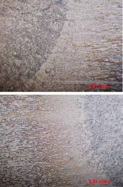
Figure 3: Two photomicrographs show the effect of changing the shielding gas when using GTAW to weld ZERON 100. The top photo shows the microstructure in the heat-affected zone using 100 percent argon; the weld in the bottom photo was shielded by a mix of 98 percent argon/2 percent nitrogen. Both samples were etched with an electrolytic oxalic acid and stained electrolytic potassium hydroxide.
“Arc control and puddle control were important factors,” Melton said. “Dimic wanted to be sure the operators understood how to use it and get the most out of it. This project is scheduled to run about a year, so they were looking for the filler metal that was the easiest to use,” he said.
Eventually Dimic developed four welding procedures, all of which used a mix of 98 percent Ar/2 percent N for the purge gas:
- GTAW with 100 percent Ar from the torch
- GTAW with a mix of 98 percent Ar/2 percent N from the torch
- GMAW-P with a mix of 98 percent Ar/2 percent N from the torch
- FCAW-G with a mix of 75 percent Ar/25 percent CO2 from the torch
“We have records of all these and found that even changing something small, such as switching from 100 percent argon to 98 percent argon/2 percent nitrogen, changes the microstructure, contributing to a better metal blend in the heat-affected zone,” Maxwell said. See Figure 3.
Maxwell also said that the pulsed-spray transfer process, which Dimic had used previously on mild steel but not stainless, performed well, providing a good balance between heat and penetration.
“It’s a very wet process, and doesn’t penetrate too deeply, but it does a good job,” Maxwell said. “It doesn’t transfer as much heat as other processes, but it worked well for this application. The only drawback is the learning curve, which is quite challenging for the welder.”
It’s a vast project, one that will take about a year to complete. That said, it is proceeding on schedule. The process development, process qualification record (PQR), ASTM G48 test results, and the in-house training program came together, and Riker is confident Dimic will have the loeds ready before the targeted deadline.
Meeting the Target Date (and Location)
The project doesn’t end when the loeds are finished. The second phase, transportation and installation, might actually be more difficult and nerve-racking than the build phase. The build phase has the usual remedies for any problems that crop up, such as cutting out a bad weld and starting over. The second phase, which will be handled by a company that specializes in transportation and installation of offshore structures, doesn’t have much margin for error.
“After we test-fit them, we’ll disassemble them for transportation to Long Beach Harbor, where they are to be
refit, finalized with the last of the welds, loaded onto a barge, and then barged south to San Onofre,” Riker said. “At the end of that little journey, they have to be dropped very precisely into the water. The tolerance for the target location is ± 2 in.”About the Author

About the Publication
subscribe now

The Tube and Pipe Journal became the first magazine dedicated to serving the metal tube and pipe industry in 1990. Today, it remains the only North American publication devoted to this industry, and it has become the most trusted source of information for tube and pipe professionals.
start your free subscription- Stay connected from anywhere

Easily access valuable industry resources now with full access to the digital edition of The Fabricator.

Easily access valuable industry resources now with full access to the digital edition of The Welder.

Easily access valuable industry resources now with full access to the digital edition of The Tube and Pipe Journal.

Easily access valuable industry resources now with full access to the digital edition of The Fabricator en Español.
- Podcasting

In this episode of The Fabricator Podcast, Caleb Chamberlain, co-founder and CEO of OSH Cut, discusses his company’s...
- Trending Articles
1
Team Industries names director of advanced technology and manufacturing

2
Orbital tube welding webinar to be held April 23

3
Chain hoist offers 60-ft. remote control range

4
Push-feeding saw station cuts nonferrous metals

5
Corrosion-inhibiting coating can be peeled off after use
