


On the level: An introduction to part leveling
Parts leveling eliminates the distortion effects of upstream processes
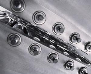
Figure 1A hydraulic roller leveler works material to level parts.
When metal is formed or cut, stresses occur. All thermal cutting processes, from oxyfuel and plasma cutting to advanced laser systems, put stress into metal. The processes generate an enormous temperature difference within the part, which leads to tensions in the material and distortion at the edges as the part cools. Even cold processes like punching and blanking with a press can release existing tensions in the material. The result is a part that may not be perfectly flat.
This is where hydraulic part levelers come into the picture (seeFigure 1). The process is straightforward and, if performed correctly, levels parts with high precision.
Principles of Part Leveling
Leveling bends metal through a series of work rolls that cause plastic-elastic deformation, with work rolls exerting alternating bending forces. The intensity of bending, or penetration of the rolls in the metal, gradually reduces as parts move toward the machine exit. The exit rolls, in fact, should exert no pressure at all, but merely maintain evenness and eliminate springback effects from previous work rolls.
The more work rolls, the more bending and deformation occur to produce a flat state. The higher the flatness requirements are, the more rolls are required (though other factors come into play as well, including material tensile strength). At the inlet, the machine's rolls put bending pressure over the entire width of the part. The bend size and, accordingly, the deflections must decrease as the part reaches the exit rolls; once the part exits the machine, the part springs back into a flat state.
Roll spacing is especially important. Consider a part entering the machine. After the first roll applies pressure to the part, the material naturally springs back before reaching the next roll. The farther apart those rolls are, the more springback there can be. For this reason, rolls in a leveler should be placed as close together as possible so that they can take out material stress, minimize springback, and ensure the part exits in a flat state.
In general, more alternating bending rolls—with one roll set bending in one direction and another roll set bending in another direction—leads to improved leveling results. Five sets of work rolls usually is considered a minimum to achieve an adequate flatness, though so few rolls may produce a part with a kind of “raw evenness,” flat enough for some applications but not others.
Thin material usually requires more working rolls than thicker materials, simply because thin metal typically has more stringent flatness requirements. For instance, metal fabricators in the aerospace business often level aluminum parts 3 mm thick, which require a flatness of about ±0.1 mm over an entire meter. With thicker gauges come different requirements. Fabricators serving the construction industry, for instance, might level oxyfuel-cut parts up to 50 mm thick and need ±3-mm flatness over a meter (seeFigure 2).
The most important parameter is part thickness. If a sheet is 30 mm thick, the inlet valve should be adjusted to less than 30 mm while the outlet valve should be approximately equal to the material thickness.
Basic Troubleshooting
In practice, some sheet metal parts still are deformed after being leveled. This happens for three main reasons. First, if the direction of the curvature is the same as the initial condition, the leveler inlet was adjusted too low, with the top and bottom rolls spaced (that is, the roll gap) too far apart. This underleveled condition can be resolved by a new run using a stronger adjustment on the inlet, with a slightly smaller gap between upper and lower rolls.
Second, if the direction of the curvature is the opposite of the initial condition, the leveler was adjusted too high. To remedy this overleveled condition, the operator should check whether the outlet value equals the part's thickness and, if necessary, choose a lower adjustment on the inlet, this time with a slightly larger roll gap.
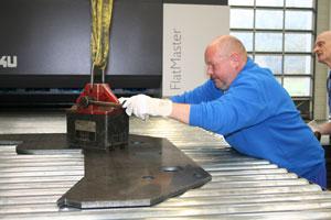
Figure 2Generally, thick parts have less stringent leveling requirements and require fewer rolls than thin parts.
Third, a part may not be levelable on the existing leveler. In this case, the manufacturer should examine whether other levelers can do better, or if the material in use meets the requirements for leveling.
Hardened metals, for instance, may or may not meet these requirements. High-tensile-strength material requires higher forces to reach its yield point, and those higher leveling forces also affect the machine design and leveling rollers. A rigid machine design ensures the operation will both achieve the required leveling result and endure years of use. If stress remains in the material after hardening, it is, to a certain extent, levelable. To level such parts however requires high forces combined with small roll diameters.
The smaller the roll spacing and the shorter the diameter of the rolls themselves, the better the result, as long as a rigid machine gives those rolls sufficient support to avoid deflection. The narrow roll spacing and smaller roll diameters exert stronger force and, hence, stronger bends.
The arrangement helps the leveler apply enough force to reach the material's yield point quickly, after which plastic deformation ensues.
In other words, the rigid arrangement makes it easier for the rolls to do their work and bend material. In fact, all metals with a minimum stress rate of 5 percent and a defined yield point can be leveled.
Put another way, if it can be bent, it can be leveled.
Upon receiving a part, the operator checks the controller to see if a program for an identical or similar material is in the database. If the controller has the program, those parameters serve as his starting point. If the material is not in the database, the operator sets parameters for the inlet and exit rolls. Exit rolls should equal the material thickness, while the inlet space should be slightly less (several 10ths of a millimeter) at the entrance.
2. Do a Trial Run
With the parameters set, the operator pushes a button, and the upper and lower rollers move into position. The machine starts feeding the part into the space between the upper and lower leveling bank. Once the part exits the machine, sensors indicate to the controller that the part has finished, after which the banks of rollers disengage. The upper roller set will move up, and the part is brought back through the machine to the entrance. This allows the operator (and crane, if parts are heavy) to work only at the inlet side of the machine (see Figure 1).
3. Inspect the Part
The operator measures the flatness. If the part is flat enough, the operation can commence. If it's not, the operator adjusts the inlet or outlet settings as necessary (see Basic Troubleshooting section) and runs the part again.

Figure 1Click image to view largerAn operator uses a crane to place a thick, oxyfuel-cut part onto the leveler.
About the Author
About the Publication

subscribe now

The Fabricator is North America's leading magazine for the metal forming and fabricating industry. The magazine delivers the news, technical articles, and case histories that enable fabricators to do their jobs more efficiently. The Fabricator has served the industry since 1970.
start your free subscription- Stay connected from anywhere

Easily access valuable industry resources now with full access to the digital edition of The Fabricator.

Easily access valuable industry resources now with full access to the digital edition of The Welder.

Easily access valuable industry resources now with full access to the digital edition of The Tube and Pipe Journal.

Easily access valuable industry resources now with full access to the digital edition of The Fabricator en Español.
- Podcasting

In this episode of The Fabricator Podcast, Caleb Chamberlain, co-founder and CEO of OSH Cut, discusses his company’s...
- Trending Articles
1
How to set a press brake backgauge manually

2
Capturing, recording equipment inspection data for FMEA

3
Tips for creating sheet metal tubes with perforations

4
Are two heads better than one in fiber laser cutting?

5
Hypertherm Associates implements Rapyuta Robotics AMRs in warehouse
