


Vice President
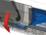
Figure 1 Click on images to view larger A single-beam system folds a part down in the negative (left) and up in the positive direction.
Press brakes have ruled the roost in North American manufacturing when it comes to bending blanks into their finished part form. But they are just one option among the various bending systems on the market; folding machines and automated panel-bending cells are other options.
In the past most bending systems were limited to bending a flange up in one direction. To achieve up and down bends without flipping the blank required either a fully automated bending system or a double-beam folding machine. Recent advancements, however, have allowed a folding machine to perform compound, bidirectional bends—up and down without flipping the blank—with a single beam (seeFigure 1).
Press brakes and folding machines handle the workpiece differently. On a press brake, the flange is gauged and the operator supports the part. On a folding machine, it's the other way around: The part is gauged and supported on the sheet-support system, and the flange is turned.
During folding, the metal is positioned on the sheet-support backgauging system. The upper and lower clamping beams clamp the metal, and a folding beam—with a "blade" tool contacting the material—forms the programmed flange angle. Servo-electric folding systems clamp to position instead of pressure; the machine's closed-loop control ensures the Y1 and Y2 axes always remain parallel to thefolding beam. If the control tells the machine to clamp to 0.050 inch, it will move to exactly 0.050 in., no more and no less. This eliminates, among other things, positioning issues when folding geometries such as open hems.
The beam—which can swing to position within 0.1 degree—determines the angle. For this reason, most folding applications can work with one universal tooling set (seeFigure 2).
Unlike press brakes, folding machines do not bend with tonnage. Bending force comes from a swinging beam, not from tonnage exerted by a press brake's hydraulic cylinders. Because the swinging beam does most of the work, a folding machine can bend thick material without hydraulics. Today some all-electric servo systems can bend up to about 9-gauge (1⁄4-in.) material.
The overall dimension of the workpiece lies on the support table while the beam folds the flange. The gauging system moves the part forward and positions it for each fold. The operator checks the material against the backstop and then steps on a foot pedal to start the folding sequence. Most important, the system supports the workpiece—be it a small blank or a large panel—throughout thebend.
Why a press brake can bend in only one direction is obvious: The bend geometry is based on the tooling. Unless specialized punch and die sets, like offset tools, are used, most press brakes make one bend per hit, in the upward direction.
Why do conventional single-beam folding systems bend only upward? This is because the leading edge of the bend changes depending on the direction of the bend—top of the beam's blade for positive bends, the blade's bottom for negative bends—and each requires the beam to pivot around a slightly different point to maintain the same bend-line position throughout the operation. This is why compoundbending in one setup traditionally has required two beams, the first moving on a pivot point positioned for the leading edge during an upward bend, the second on another pivot point for the downward bend.
What if that pivot point could change during operation? Consider a beam with a blade 0.6 in. (15 mm) wide. Again, bending up, the leading edge is on the top side of the beam blade tool; on the way down, it's on the bottom, 0.6 in. away from the top leading edge. This means the pivot point—the point from which the beam swings up and down—must move by 0.6 in.
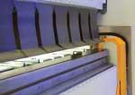
Figure 2 Click on image to view larger In folding, most applications work with universal tooling.
To make up and down bending work with a single beam, two things must happen. First, as explained, the beam pivot point must change. Second, the beam must extend outward, away from the machine, to get around any flanges that have already been bent. Say the machine has just bent up a 5-in. flange; now the machine needs to bend down a 2-in. flange. To get into position, the folding beam must moveaway from the machine 5 in. to get around the first flange, then come back in to perform the downward bend.
As shown in Figure 3, the beam and blade (in gray) start above the workpiece, positioned to make a downward 90-degree bend. Once it makes the bend, the beam swings down, moves outward to clear the bent flange, and moves its pivot point, changing the leading edge to the opposite side of the blade tool. If the beam did not move to another pivot point, the beam blade literallywould crash into the folding machine tooling (in blue). In the figure, envision the left edge of the gray blade in No. 1 swinging 180 degrees around the same central pivot point; the blade would crash into the folding machine before rotating the full 180 degrees—hence, the need to change the pivot point outward.
Today certain folding systems actually can move the pivot point between up and down bends. Some use hydraulic cylinders; others use air pressure that rotates an eccentric the width of the blade tool. This, combined with the in-and-out beam motion to get around flanges, makes compound bending with a single beam possible. Using a single beam maximizes "free space" within the working envelope,making myriad bend geometries possible.
When using a bidirectional folding system, the operator stands next to the backgauge/sheet-support system, opposite from the tooling and folding beam. He then locates the part against the gauging fingers designed into the sheet-support table (see Figure 4). The support system adjusts to the size of the part; the table surface area decreases for narrow parts and increases forlarger blanks (see Figure 5). The operator does not have to lift or support the blank.
Bidirectional, single-beam systems also handle deflection in a new way. Modern folding machines, like press brakes, have crowning systems that calculate and compensate for deflection during the bend. These systems have made great strides in ensuring every bend is an accurate bend.
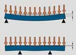
An alternative approach, however, does not use a crowning system. In a conventional folding beam, the center—the farthest distance from the end supports that connect to the machine frame—experiences the most deflection. However, some beams today are engineered to eliminate deflection effects, increasing rigidity with a beam-in-beam design (see Figure 6). Basically, the beamhas a smaller beam welded and gusseted inside it.
Single-beam, bidirectional folding may well evolve into commonplace technology, with great potential in an industry starved for skilled labor. In the past a press brake operator would read the drawing, pull the tooling, set up the brake, bend the part to specification, inspect the part, and maintain the machine tool. Now these duties may be shared among three or four different people.
Also, press brakes often require more than one operator, particularly for large parts. Additional material handling means additional costs. Today options exist to eliminate that material handling from the equation.

The Fabricator is North America's leading magazine for the metal forming and fabricating industry. The magazine delivers the news, technical articles, and case histories that enable fabricators to do their jobs more efficiently. The Fabricator has served the industry since 1970.
start your free subscription
Easily access valuable industry resources now with full access to the digital edition of The Fabricator.

Easily access valuable industry resources now with full access to the digital edition of The Welder.

Easily access valuable industry resources now with full access to the digital edition of The Tube and Pipe Journal.

Easily access valuable industry resources now with full access to the digital edition of The Fabricator en Español.
In this episode of The Fabricator Podcast, Caleb Chamberlain, co-founder and CEO of OSH Cut, discusses his company’s...


