


Executive Vice President
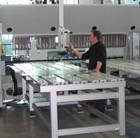
Figure 1: Folding technology allows one operator to bend large panels without breaking his back. But the technology has evolved to make economic sense for more than just large parts.
A job shop will invest a significant amount of money automating its blanking operation, or the “first-ops” department. Material towers, which automatically feed various cutting or punching systems, often are employed, along with dynamic nesting systems that further the goal of reducing the effort it takes to produce exactly what is needed, when it is needed, while maintaining exacting controlover production requirements. If a job calls for five cabinets requiring 10 parts each, the lasers cut all 10 parts for each cabinet, or a total of 50 parts, so they can flow to subsequent operations.
Then, parts pile up in the bending department.
Cutting automation has helped lean-out fabricators significantly, even job shops with high-mix, low-volume operations. But most cut parts must undergo forming, and in this arena the press brake has always dominated—for good reason. The press brake is a flexible, cost-effective forming system that can bend everything from small, intricate components to massive plate. But, unlike the laser,press brakes require significant setup time, and parts often are bulky or require flipping. For these reasons, bending is not nearly as efficient as the blanking process, which basically is why that pile of parts—the large work-in-process buffer—has been necessary.
Newer brakes with quick-change tools, modern controls, and offline programming have made significant strides reducing setup time, but the nature of brake operation makes it difficult to improve efficiency of the actual forming process. In addition, older brakes also can have extensive setup times and require repeated part tryouts, making setup times 40 minutes, an hour, or even more.Fortunately, the press brake isn’t the only bending technology out there.
Fabricators traditionally have used a folding system to bend parts that are difficult for operators to handle on a press brake. If a large, thin panel requiring a flange at one end needs multiple operators to handle the part during the bending cycle, the shop may have purchased a folding system to handle the job. The folder allows just one operator to bend these large panels without breakinghis back.
The part is positioned against the backgauge, the clamping beam tools hold the blank in place, and the folding beam swings up to bend the flange to the desired angle. This approach has many advantages. Unlike a press brake—where a punch pushes the metal into a die to the desired angle, swinging the rest of the part through the air—the folding system bends the flange while keeping the rest ofthe part stationary. It’s a natural way to bend, like folding paper (see Figure 1 and Figure 2).
Forming with a press brake relies on both sides of the material. If one part’s thickness varies from the next, the bend angles also will differ. The same effect occurs with hardness variations. Hardness affects not only springback, but also the inside bend radius. For accurate bends, these material variations require a different material penetration than what the control calculated, socorrections need to be made, either automatically or manually.
Folding ignores most of these material variations. Because the folding beam tool contacts only the outside surface of the material to make the bend, thickness variations along with differing inside bend radius caused by hardness variations have no impact on the angle of bend. Only springback is corrected for by a slight overbend if necessary, automatically calculated and applied by thecontrol.
In folding, tooling is independent of material thickness. A folder’s tooling can form everything from its maximum capacity rating on down. There is no need to have a different tool set for each material thickness; the machine mechanically changes the length of the folding beam’s swing and its pivot point to adjust to different thicknesses. Changing from 0.25 in. to 26 gauge, for example,requires a three-second or less machine adjustment. The folding blades do the work while the clamping beam tools hold down the part in the gauged position (see Figure 3).
When tool changes are required, it is typically to resize their length to accommodate part size. The clamping beam and folding beam tools are precision-ground and segmented. Various segments combine to handle the different part sizes. A typical tool setup is made for the longest side: The short sides will form first, followed by the longest sides. Corner tools will allow for any return bendson short sides while the long sides are being finished.
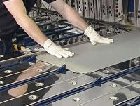
Figure 4: A folding system can use up to four positioning fingers, together providing up to 12 axes of backgauging: X1 through X4; R1 through R4; and Z1 through Z4.
Like the clamping beam tools, the folding beam tools also can be stacked to the bend length, though jobs rarely require this because a long folding blade usually can handle any equal or narrower bend length. But in the case of a weld tab or other form away from the bend line, stacking the blades to the exact bend length works best. Tab tools can form the tabs and flange in one bend, and othersetups are easily performed if required.
Perhaps most significant is the way a folder gauges the part. On a press brake, the operator slides a flat sheet’s edge against the backgauge and makes the first bend. For the next bend, the backgauge moves to the desired gauge dimension, and the operator slides the previously bent flange against it. But what if that bend angle is off? Because the operator is gauging the part on aninaccurately bent flange, a snowball effect of tolerance buildup ensures that the next bend will be a little more off, the following bend even more off, and so on. That first bend may have been well within tolerance, but as the operator gauges off the previously bent flange, tolerance buildup throws off part geometry significantly by the final bend. Each bend has used a different datum point, andthe part ends up in the scrap bucket.
The folder, on the other hand, gauges off the same datum point for each bend per side, and gauges the overall part size, not the flange (see Figure 4 and Figure 5). Consider a simple part requiring two 90-degree bends on one side. Backgauge fingers move the workpiece into position, clamping beam tools hold the material in place, and the beam swings up toproduce the first bend. For some reason, though, it underbends ever so slightly, although not enough to throw the part out of tolerance. From this point, however, that first flange never touches a backgauge, so its inaccuracy has no effect on the subsequent bends. Using the same datum point, the fingers move the part forward, repositioning it for the second bend with no accumulated error.
A folding machine presented all these advantages a decade ago, but one disadvantage prevented the technology from being economically feasible for many applications: A folding system often was slower than a less expensive press brake. For certain large parts, however, the folder has made economic sense for years. Not only do such parts create an ergonomic nightmare and an outrightsafety hazard for operators at the press brake, the act of manipulating large parts at the brake makes for very slow cycle times, so a folder has indeed had the ability to form such large parts faster.
But this wasn’t the case for most average-size sheet metal parts. The folding beam formed relatively slowly, and the typical folding system was monodirectional, bending only in one direction. As soon as a part flip was required, justifying a folder became more difficult, because the initial justification for folding—improved ergonomics—was lost. Unless the parts were the perfect size andquantity, the forming machine choice often was the lower-cost provider, not the best process provider.
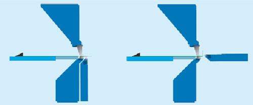
Four advances in recent years have made folders suitable for more than just large, unwieldy workpieces. First, servo-electric motors now drive the folding beam at extremely high speeds, often up to 150 degrees a second. This effectively eliminates the speed disadvantage.
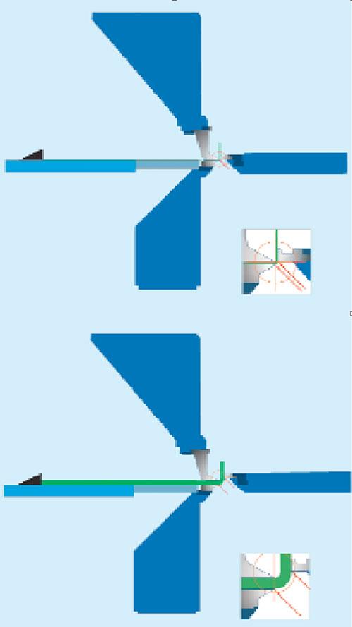
Second, single-beam folding systems now bend bidirectionally, both up and down. This eliminates the difficult part-flipping earlier systems required. The beam swings up to form an up-bend, then moves out and around the previously formed flange, repositioning itself against the part to make a down-bend, and so on.
Third, folders now have automatic tool change. Robotic arms position clamping and folding beam tools for the next job. Setup time between jobs is reduced to less than three minutes and is performed while the operator is making ready for the next run.
Fourth, folders have sufficient backgauging to handle very complex parts. A modern press brake typically has a four-axis backgauge: X1 - X2 for flange depth and Z1 - Z2, which move both fingers laterally across the bed length. Six-axis systems usually include R1 - R2, which raise and lower the gauge fingers. A folder, on the other hand, may have as many as 12 axes of motion across fourbackgauge fingers: X1 - X4, R1 - R4, and Z1 - Z4.
Multiaxis backgauges allow a folder to make very complex forms quickly. Classic examples are parts on which bend lines have no parallel edge to gauge against. The X axes must offset to triangulate the gauging points and properly position the bend line.
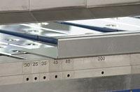
Figure 5: Here, the fingers moved a specified distance to form the first bend, and then move again for the second. Because the folder does not gauge from a previously bent flange, it avoids tolerance buildup.
But additional backgauging axes allow a folder to tackle certain jobs that are even more complex, an example being gauging off of a bump-formed edge with multiple flange heights. Such a part could have two adjacent bumped-form flanges on each side, with the left flange higher than the right flange. The two formed flanges on one side of the part face identical flanges of different heights onthe opposite side. The distance between the facing flanges (facing each other on opposite sides of the part) must be accurately held; if it is not, the out-of-tolerance component will wreak havoc on downstream weld and assembly operations.
To form this part accurately, backgauge fingers move in X1 and X3, gauging against the unformed edge and offsetting their position to the differing flange lengths. As the two flanges are bump-formed on the opposite side, each finger positions independently for different form depths. Next the part is rotated. At this point the top of those formed flanges becomes the datum point as the tolerancebetween these facing flanges must be held. X1 and X3 must again accurately position the part for the bump form on the opposite side, but the R1 and R3 axes must also adjust their height to gauge off the top edge of the previously bumped forms.
Only with these gauging points can the part’s accuracy be held. In addition, the ergonomic advantages of such a system quickly become apparent when dealing with such a difficult part.
Like any process, folding isn’t the answer for everything. A single-beam bidirectional system is applicable only up to 0.375 in. thick. Beyond that, minimum flange lengths are greater than the system’s workaround dimension. Monodirectional systems easily handle 0.375 to 0.75 in., but with the influx of inexpensive, high-tonnage press brakes, the fit for a folder must be perfect for itsjustification.
Small, complex bends often are better-suited to press brakes. A computer chassis, for example, has small form details that do not fit well with the size of a folder’s tooling. A folder’s clamping beam tool and the folding blades have a larger surface contact area, which makes forming such small geometries difficult if not impossible. Tiny return bends, offsets, inside lances, and other formsare all better-suited to the small tools that only a press brake can run. In addition, studs, nuts, countersinks, and threads that are set before the part is formed can get in the way of the folder’s tools; they must either be outside of the tool area, or reliefs need to be provided to clear these details.
The folder also stumbles to form certain small geometries, such as small 90-degree offsets and smaller hat channels, in the same way as a high-tonnage press brake with single-hit tools. All of these examples must be given careful consideration to make certain the gains of a folder are not immediately undone by profile difficulties.
Stacks of parts—flat blanks and bent components— represent work-in-process buffers of highly variable job shop operations and are necessary only in job shops that have not reached the ideal of single-piece flow. While single-piece flow may not be attainable in an extremely high-mix situation, it is a lean manufacturing concept worth striving for. The closer a shop gets to single-piece flow,the leaner and more efficient the operation will be.
For a lot of 100 cabinets of five parts, the laser doesn’t need to cut 100 of each part, forcing operators to lug a heap of 500 components to downstream operations. Instead, the lasers produce only what downstream operations need. Production scheduling and dynamic nesting allow for precise control over which parts are nested together and when they are cut. One or two sheets may contain all thecomponents required to produce a single cabinet.
When the parts flow downstream to forming, two factors must be considered. The first is the time it takes to set up for the form; the second is the amount of time it takes to make the form. The utilization and efficiency of the bending operation must be balanced against the productivity of the first-ops system preceding it.
The folder control is tied into the scheduling system, so it knows what is next in queue. The automatic tool changer sets up the tooling while the operator is getting set for the run. When the five parts emerge from the upstream operation, the machine is ready to begin the forming operation.
The operator picks up the first piece and begins folding. If tool changes are needed between the parts, the machine automatically does so, and production continues. With the ergonomic ease with which the parts are formed, the elimination of flipping, and the faster forming speeds attainable by folding, the process time can be substantially reduced, more closely matching the time it takes thelaser to profile them. The parts that go into the kit are stacked together and fed downstream—again, as one kit—to welding, grinding, painting, and final assembly. And the operation continues. Such flow obviously requires first-part, good-part, and here folding can help, because the technology reduces part forming variability.
Attaining such flow is a lofty goal, but modern folding technology can bring shops closer to achieving it. The key is to ensure that parts never stop moving. To form every part needed for an assembly, one after the other, means that every part will be different from the one before it. The only way to make this kind of flow a reality is to significantly reduce setup time. Thiswill increase the machine utilization, and the increased forming velocity will increase machine efficiency. These two factors combine to create a very lean forming system.

The Fabricator is North America's leading magazine for the metal forming and fabricating industry. The magazine delivers the news, technical articles, and case histories that enable fabricators to do their jobs more efficiently. The Fabricator has served the industry since 1970.
start your free subscription
Easily access valuable industry resources now with full access to the digital edition of The Fabricator.

Easily access valuable industry resources now with full access to the digital edition of The Welder.

Easily access valuable industry resources now with full access to the digital edition of The Tube and Pipe Journal.

Easily access valuable industry resources now with full access to the digital edition of The Fabricator en Español.
In this podcast episode, Brian Steel, CEO of Cadrex Manufacturing, discusses the challenges of acquiring, merging, and integrating...


