


Graduate Research Assistant, ERC/NSM
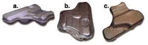
Figure 1.
Editor's Note: This column was prepared by Serhat Kaya, graduate research associate at the Engineering Research Center for Net Shape Manufacturing (ERC/NSM), The Ohio State University, Professor Taylan Altan, director.
In the July/August 2002 (p. 54) issue we addressed material selection for automotive fuel tanks. This column covers manufacturing processes for fuel tank upper and lower shells and experimental results.
In the last column we compared the use of stainless steel for fuel tanks with plastic and other metals, such as high-strength steel (HSS) and aluminum. Stainless steel's main advantages are its high corrosion resistance, greater formability, and dent resistance as a result of high strain hardening.
After selecting the appropriate material for a hydroforming process, the question to ask is, How do I know which process to use to manufacture the upper and the lower shells of the fuel tanks? Choosing the appropriate process to manufacture both shells is important. Figure 1 shows the upper and lower shell of an automobile fuel tank.1Hydroforming (the basics of hydroforming were discussed in the March/April 2002 column, p. 42) is practical when conventional deep drawing fails to form a fracture-free part.
However, when the draw depth is shallow and the part is not complex, hydroforming is unnecessary because its cycle time is longer compared to conventional deep drawing.
Now, the question to ask is whether it's necessary to use hydroforming to form both parts. To answer this question, Friebe2 conducted finite element analysis (FEA) at the International Conference on Hydroforming as part of a development project to determine maximum strain after deformation.
Results indicate that the more expensive hydroforming is unnecessary to form the upper shell of the fuel tank. Figure 2 shows the FEA results, with the different colors representing part thickness changes after deformation. Light-blue sections represent maximum thinning areas shown with thickness values of 0.505 millimeter. The original sheet thickness is 0.6 mm. This result shows that the part can be made more economically by conventional deep drawing.
The process simulation and trials also demonstrate that because a conventionally deep-drawn, 0.8-mm-thick part is in the safe region, this sheet can be replaced with a 0.6-mm-thick sheet, resulting in a 25 percent weight reduction and a successful part.
Because of the lower shell's geometric complexity, the hydroforming process is needed to obtain a fracture-free part. Maximum draw depth is 80 mm in the upper shell and 150 mm in the lower shell. Differences in part designs show that the lower shell requires either a material with better formability or a different process, such as hydroforming, to form it with less thinning and no fracture.
The study3found that using the proper process for the part has a big impact on cost-effectiveness. Figure 3 compares material thickness values, weight, and capacities for fuel tanks manufactured from plastic and steel.
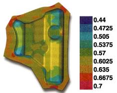
Figure 2.
The comparisons show that steel tanks provide lighter and higher capacity than plastic. The main advantage of a steel tank is that gas fumes or additives do not leak, which helps to minimize ground water pollution.
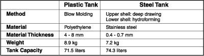
Figure 3.


The Fabricator is North America's leading magazine for the metal forming and fabricating industry. The magazine delivers the news, technical articles, and case histories that enable fabricators to do their jobs more efficiently. The Fabricator has served the industry since 1970.
start your free subscription
Easily access valuable industry resources now with full access to the digital edition of The Fabricator.

Easily access valuable industry resources now with full access to the digital edition of The Welder.

Easily access valuable industry resources now with full access to the digital edition of The Tube and Pipe Journal.

Easily access valuable industry resources now with full access to the digital edition of The Fabricator en Español.
In this episode of The Fabricator Podcast, Caleb Chamberlain, co-founder and CEO of OSH Cut, discusses his company’s...


