


Project Engineer
Cost, weight, performance, dimensional stability, and part count reduction are important considerations when determining if hydroforming a part makes economic sense.
Cost-effectively produced, correctly positioned holes are essential, functional requirements in nearly all structural automotive components. They serve many purposes and accommodate various fastener types—including self-threading screws, pushpins, wiring clips, plug welding—and provide clearance. Holes allow other components to be attached to the hydroformed part and the hydroformed part to be attached to the vehicle structure. How these holes are made greatly influences total part cost.
Holes can be cut into a part in almost any quantity, shape, profile, size, and position desired. Hole-producing methods include drilling/milling, laser or plasma cutting, flow drilling, and punching in the die (hydropiercing), or post-piercing. All of the holes in a hydroformed part can be made using one technique or several as needed to satisfy all hole design requirements.
The main factors to consider when choosing the most suitable method for making each hole are repeatable and accurate positioning, cost, , hole shape and profile—indentation or not and extra material extruded into the hole for self-threading fasteners— and slug positioning and removal.
|
Position |
Repeatability |
Cost |
Hole Profile |
Slug Removal |
Flexibility |
|
|
Mill/Drill |
4 |
3 |
1 |
2 |
5 |
3 |
|
Laser Cut |
3 |
3 |
2 |
3 |
4 |
5 |
|
Plasma Cut |
3 |
3 |
3 |
3 |
4 |
5 |
|
Flow Drill |
3 |
3 |
1 |
4 |
5 |
3 |
|
Post-piercing |
2 near part end |
3 |
2 |
5 |
5 |
3 |
|
Hydropierce |
5 |
5 |
5 |
3 |
3 |
3 |
Figure 1 rates each hole forming method's performance in the key areas, with 1 being low and 5 being high.
Note: This chart gives a general relative assessment of the different hole forming methods and their characteristics. Specific part designs may change the relativity somewhat. Anyone seeking more information about or wishing to discuss these ratings should contact the author.
The most dimensionally accurate, stable, and economical way to produce holes in a hydroformed part is to punch them in the hydroforming die during the forming cycle. This method is similar conceptually to the way holes are made in stampings.
Part or die design requirements may dictate using other methods. For example, when mounting locations are cut in the die for punch unit placement, the resulting reduced structural die strength may be inadequate to withstand the forces exerted at very high hydroforming pressures. Some holes cannot be punched during hydroforming because of insufficient room in the tool or unsuitable hole requirements, such as when a hole extends through a cross-section corner.
In-die hole punching abilities vary from one company to another. As more hydroforming companies improve their in-die hole punching capabilities, it seems likely that pressure to reduce cost will force this method to become more prevalent.
The rest of this section focuses on the hydropiercing options, since most common design conditions can be met at the lowest cost using this method.
 |
| Figure 2 |
Hydropiercing can produce various hole styles, including the three shown below. In the first two examples, the slug is attached. This is done to prevent the slug from floating free and controllably, which causes tooling problems, marks in the surface of subsequent parts, or inexplicable rattling problems in the vehicle, among other difficulties.
Many holes produce a slug that is 6 mm or less in diameter. Such slugs weigh very little, and any mass benefit gained from removing them is small compared to potential problems that can result from removal.
Figure 2 shows a pierced-hole cross section. Because fluid acts as a less than perfect die button, some indentation occurs around the hole's edge. Among the applications for this hole style are clips, clearance, and draining. A punching method has been developed that can make drain holes that have no net indentation.
 |
| Figure 3 |
The hole in Figure 3 was produced with a punch that pierces a small pilot hole and pushes material into the part to form an extrusion. This method provides a lead-in and a longer land for better self-threading fastener engagement, which is this hole type's most common purpose. It may give the casual observer the impression that hydropiercing causes more inherent indentation than it truly does.
Figure 4 shows a slug being pushed out from the cavity by internal pressure. As shown in the illustration, no indentation is present around the hole. The slug is disposed of outside the die.
 |
| Figure 4 |
Fluid leakage around each of these hole styles can be very small, even zero, when properly designed, thus allowing many holes to be punched in the same part while maintaining needed pressure in the tube. A common concern among people unfamiliar with hydroform punching is how to maintain water pressure in the tube after the holes are punched. The normal practice in producing the first two hole styles is to leave the punch in each hole to act as a very effective plug until all punching is complete and then withdraw them after the need for internal pressure has passed. The hole style in Figure 4 can be made to seal well also, using a different mechanism. Some production dies have as many as 64 holes of many shapes and sizes in a 1,800-mm-long part.
 |
| Figure 5 |
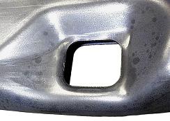
Holes also can be produced by piercing through both walls of the tube and carrying the slugs out of the tube to prevent the problems mentioned previously. In this case, a small amount of indentation is likely to be present around at least one hole. Using this approach requires two opposing holes made with punches mounted on two cylinders, although they can differ in size. Figure 5 shows a part with a pair of such holes where the walls that are too close to allow slugs to be retained and folded to the side.
Both this method and the one used to produce the holes in Figure 4 detach the slug from the part, reducing part weight when the slugs are large, preventing interference with other parts in an assembly, and allowing a fastener to fit against the inside surface of the tube around the hole. Although provision has to be made in the die, the part cost is low compared to other methods described in the table. An example is shown in Figure 6.
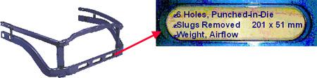 |
| Figure 6 |
Other hole types that typically are made after hydroforming also may be performed in-die to minimize part cost, but each situation must be reviewed separately to assess feasibility.
Many different hole shapes can be produced, including round, oval, rectangular, and hexagonal. Hole size is limited only by what is reasonable for the part geometry.
High forming pressures reduce the indentation around holes like those in Figures 2 and 3. However, high pressure requires larger punching units, which limits how closely the holes can be grouped together.
Another important consideration with high pressure is the die remaining strong enough to resist the large forces produced at maximum internal pressure. If it isn't strong enough to withstand repeated high pressure, the tool will crack and break. Because installing punch units requires cutting suitable openings for mounting, this strength requirement also can restrict hole count and placement, leading to more holes being cut post-hydroforming.
Maximum flexibility in hydropiercing is important to produce the best and most economical product. Holes that cannot be hydropierced must be done in a secondary cutting or piercing operation at additional cost and reduced positional accuracy and repeatability. Wear inserts and other separate parts that impede punch unit placement can affect flexibility.


The Tube and Pipe Journal became the first magazine dedicated to serving the metal tube and pipe industry in 1990. Today, it remains the only North American publication devoted to this industry, and it has become the most trusted source of information for tube and pipe professionals.
start your free subscription
Easily access valuable industry resources now with full access to the digital edition of The Fabricator.

Easily access valuable industry resources now with full access to the digital edition of The Welder.

Easily access valuable industry resources now with full access to the digital edition of The Tube and Pipe Journal.

Easily access valuable industry resources now with full access to the digital edition of The Fabricator en Español.
In this episode of The Fabricator Podcast, Caleb Chamberlain, co-founder and CEO of OSH Cut, discusses his company’s...


