


Tube hydroforming for expanded design options
Knowing the capabilities, limitations, and misconceptions is key to understanding hydroforming's potential
 |
Much of the attention on hydroforming concerns automotive components and focuses on weight savings, strength improvements, and reducing the number of parts. While all of these are advantages gained through hydroforming, a less commonly discussed reason to hydroform components is more design options. In some cases, hydroforming is the only method that can generate a unique geometry in a single process or as the final step in a combination of processes.
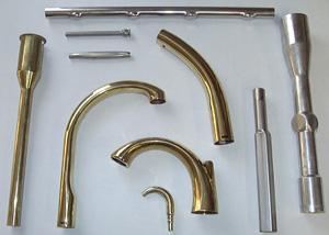
Hydroforming is useful for manufacturing many products, including faucets, handles for medical instruments, door hardware, table and chair legs, rifle scopes, and numerous sporting good components. Choosing hydroforming for these applications has less to do with weight savings and more to do with reducing the number of processing steps to produce interesting and aesthetically pleasing shapes.
Hydroformed component features can include changing cross sections with varying corner radii and curved sections. The process can produce smooth transitions between round and oval or rectangular cross sections. The cross sections can vary as the contour of the part sweeps around a changing centerline through a radius or changing spline. Features can be produced with this process that are not easily obtained by any other method.
Design limitations of hydroforming defy a simple explanation. Three questions that tend to arise with all designs are: How much can the cross section change? How tight can the corner radius be? How much will the wall thin? The answer is always, "It depends." Some limitations are driven by properties of the product material, some by the hydroforming system constraints, and others by specific design features of the final product.
Material Requirements
Engineers and part designers must consider material properties such as yield strength, ultimate strength, and allowable elongation in the design of a component. Materials commonly formed are brass, stainless steel, carbon steel, and aluminum. These materials vary widely in formability characteristics. Heat-treating operations provide more latitude in controlling the material's temper and grain size. Balance is necessary for parts that require a particular cosmetic appearance—the material must be soft enough to form and have a tight enough grain structure to prevent an orange peel surface condition.
In some cases, hydroforming a component is done in multiple steps with intermediate annealing processes between each step. This increases the total elongation of the material from starting blank to the final formed part. The expansion during each forming step can be controlled by using separate molds with incremental increases in the size of the forming cavity. Another, less consistent and less costly method is use of a single forming cavity. In the initial forming step, the forming pressure is limited and the cycle is stopped before filling the mold cavity. After annealing, the blank is formed to completion in the same cavity.
Equipment Capabilities and Limitations
One aspect of the design that has a direct impact on both the extent of formability of a feature and the amount of thinning the material will undergo is the location of the feature in relation to the part's end. Features near the end of the forming cavity can be more easily influenced by axial feeding of the material with side rams than can features at the center of the forming cavity (see Figure 1). As the feature location moves away from the end, the material has a higher tendency to lock in the mold cavity. The result is a decreased capability to feed material during the forming process. Features in this area are produced strictly by stretch and are more dependent on the material properties.
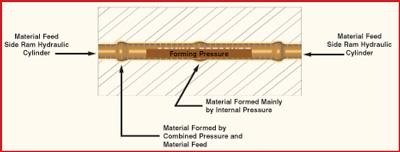 |
| Figure 1 The effect of axial feeding is greatest near the tube ends, where it assists the internal forming pressure to form part features. The effect of axial feeding diminishes with distance—the farther a feature is from the end, the less axial feeding assists in forming it. |
The geometry that can be formed is first limited by the ability to fit a blank into a mold cavity (see Figure 2). The closer the blank fits into the mold, the less forming is required. The ability to control the dimensional characteristics of the blank, including diameter and wall thickness, or to produce a blank drawn to a nonround shape, improves the range of products that can be hydroformed. In some cases, blanks are partially reduced or expanded, dented, or bent in single or multiple operations. Being able to bend complex or spline geometry increases the variety of items that can be produced.
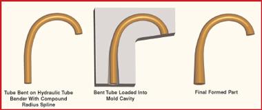 |
| Figure 2 Hydroforming usually requires at least two steps: bending the tubular blank so it fits into the mold cavity, and expanding it by hydroforming. |
One common misconception regarding hydroforming is that it results in uniform material thinning. While expanding a round tube to make a larger round shape does result in uniform wall thickness, this simply isn't true when hydroforming any other geometry. In these cases, forming is influenced by locking features in the geometry and the relationship between material lubrication and mold cavity friction. Tighter corners are filled though localized stretching and thinning of material (see Figure 3).
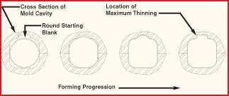 |
| Figure 3 A common misconception is that hydroformed parts have a uniform wall thickness. For nearly every hydroformed shape, the amount of wall thinning varies. The most material thinning occurs in the tightest corners. |
Most hydroforming systems consist of a hydraulic press, a high-pressure pumping system, and side hydraulic ram cylinders. The hydraulic press opens and closes a split mold cavity to allow insertion of a blank and removal of a formed part. It also holds the mold halves together as the blank is pressurized. The pumping system provides the internal forming pressure. The ram cylinders seal the ends of the tube and can feed material into the cavity by pushing against the ends of the blank.
The pressure the pumping system produces typically is the limiting factor that determines the tightest radius the system can form. A smaller radius requires more forming pressure. In some cases, on larger parts a pressure below the maximum pump pressure causes the mold to open. In this case, the limiting factor is the press tonnage. The cross-sectional area of the formed part, as viewed from above the mold cavity, multiplied by the pressure used to form the blank, must be balanced against the available tonnage of the hydraulic press system to keep the mold closed.
Paul Tauzer is engineering manager for H & H Tube & Manufacturing Co., 108 Garfield St., Vanderbilt, MI 49795, 989-983-2800, fax 989 983-4530, www.h-htube.com.
About the Author
About the Publication
subscribe now

The Tube and Pipe Journal became the first magazine dedicated to serving the metal tube and pipe industry in 1990. Today, it remains the only North American publication devoted to this industry, and it has become the most trusted source of information for tube and pipe professionals.
start your free subscription- Stay connected from anywhere

Easily access valuable industry resources now with full access to the digital edition of The Fabricator.

Easily access valuable industry resources now with full access to the digital edition of The Welder.

Easily access valuable industry resources now with full access to the digital edition of The Tube and Pipe Journal.

Easily access valuable industry resources now with full access to the digital edition of The Fabricator en Español.
- Podcasting

In this episode of The Fabricator Podcast, Caleb Chamberlain, co-founder and CEO of OSH Cut, discusses his company’s...
- Trending Articles
1
3D laser tube cutting system available in 3, 4, or 5 kW

2
Corrosion-inhibiting coating can be peeled off after use

3
Zekelman Industries to invest $120 million in Arkansas expansion

4
Brushless copper tubing cutter adjusts to ODs up to 2-1/8 in.

5
HGG Profiling Equipment names area sales manager
