


The evolution of blanking in metal fabrication
The evolution of blanking: From the shear, to the press, to the laser
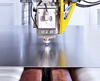
Figure 1: In this coil-fed laser blanking setup, the laser cuts a blank on a constantly moving coil. A gap in the strip conveyor moves with the laser head for material to evacuate from the kerf.
In metal forming it all starts with the blank. After straightening, the blanking operation usually is the first that touches the coil strip. The quality and cost of making that blanked sheet metal part affects other operations. In effect, blanking is the headwater of a stamping line—and for consistent flow, that headwater must consistently produce quality blanks for every process downstream.
Metal formers that stamp parts too large or complex to be fed into the press directly from a coil have relied on dedicated blanking lines. These entail a coil reel, a peeler, sheet leveler, the blanking itself, scrap evacuation, and, finally, a stacker.
Until recently stampers that needed a dedicated blanking line had two choices: a cut-to-length line or a conventional mechanical blanking press. Today two technologies are driving blanking operations in new directions: the servo-driven stamping press and, most recently, the laser (see Figure 1).
Legacy Blanking
A cut-to-length system usually produces simple blank shapes. In a line with stationary shears, the roll feed indexes the coil stock forward one step at a time, and the shear cuts the material once it is stationary. This stop-and-go motion requires the coil to be looped, in a pit or otherwise.
To cut slightly more complex shapes requires a shear that either rotates or is mounted in a cassette. By rotating or swiveling the shear, the blanking line can produce not just a straight cut but other simple shapes, like trapezoids and parallelograms. Shears mounted in cassettes can be configured to cut curves and other shapes (see Figure 2).
Flying shears, another cut-to-length technology, cut as the metal strip continuously progresses forward from the straightener without starting and stopping. This eliminates the need for a coil loop.
For more complex shapes, the traditional route has led stampers to a mechanical blanking press. These presses have been either eccentric or link-drive systems. Both of these conventional technologies, however, are limited by the kinetic energy generated by the flywheel and, thus, have a fixed motion curve. If a material requires a slower blanking speed, the entire cycle of the press slide slows as well.
This fixed motion curve has governed press parameters for decades. Material type, thickness, and geometry dictate the speed of the blanking cycle: from the approach stroke and material clamping; to when the punch first contacts the material; the ensuing elastic and plastic deformation, shearing, breakthrough, stripping; and, finally, the return stroke. Changing the speed at any stage of this cycle effectively changes the speed at every other stage.
Industry’s push toward material with high strength-to-weight ratios (in other words, material that’s thin and strong) has introduced some blanking challenges. Blanking a conventional steel, the punch shears about 80 percent of the sheet thickness, after which it breaks through. On certain grades of high-strength steel, on the other hand, the punch breaks through the sheet at only 10 percent of the material thickness. This not only causes a big impact shock on the press and dies (prematurely wearing both), it also can create edge quality problems, particularly if stroking too quickly.
Say a blanking press runs at 40 strokes per minute (SPM), so each hit takes 1.5 seconds. Hypothetically, let’s say that for one application involving conventional steel, 1 second of that 1.5-second cycle is needed for feeding, and 0.5 second is needed for the clamping and cutting. Switching to a certain grade of high-strength steel may require 1 second for clamping and cutting. This also doubles the feeding time, increasing it to 2 seconds. That produces a total cycle of 3 seconds. So now the press can run at only 20 SPM.
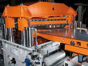
Figure 2: Shears mounted in cassettes can be arranged to cut curves and other shapes.
The servo-driven press, however, changes all this (see Figure 3). Instead of a flywheel, main motor, clutch, and counterbalance, a servo press uses a servomotor that in effect makes the slide a controllable axis.
In a traditional mechanical press, energy must be delivered from the flywheel through a clutch, down the connecting rods, which drive the ram that produces maximum tonnage at some point above bottom dead center. The main drive motor then has to get the flywheel back up to speed before the tool hits the material again. For this reason, the mechanical press’s stroke can’t be too slow, because the minimized speed of the flywheel won’t be able to provide enough energy to produce the needed force for the application.
The servo press is still a mechanical system and abides by a tonnage rating curve, so it cannot deliver full tonnage throughout the stroke like a hydraulic press can. But a servomotor, unlike a flywheel in a traditional mechanical press, provides maximum torque almost immediately.
In a blanking operation, this means that the slide can slow as necessary during clamping and cutting, but then speed up for the rest of the press cycle. In the previous example, the press can decrease its speed during clamping and cutting, going from 0.5 to 1 second. But the remainder of the stroke can remain 1 second. That’s a 2-second cycle, allowing for 30 SPM on high-strength material.
Servo presses also have programmable stroke lengths, which help increase speeds as well. A conventional mechanical blanking press might have a 350-mm stroke. That’s 700 mm of travel over one up and down cycle of the slide. Out of all that, though, only a small portion—say, 60 mm—might be used for clamping and cutting. During the rest of the stroke cycle, the strip is feeding into the press. On a servo press, the stroke length may be set to just 180 mm, or 360 mm of total slide travel during one cycle.
The slide can travel slower when it contacts the material, which is better for the die, the press, and the material. At the same time, overall throughput goes up, because the slide has less distance to travel, and it can speed up when it’s not contacting the workpiece. In a phrase, the press slide is traveling less but blanking more.
Of course, none of this matters if a blank is scratched or otherwise damaged when stacked. High-speed parts offloading is critical, because a slow stacker negates the servo press’s speed advantage. The same holds true at the leveler and at the servomotor-driven press feeds. A blanking line is only as good as its weakest link.
Today stacking system transfer mechanisms on blanking lines can move as fast as 200 meters per minute. Telescoping conveyors move the blanks close to their final drop point, where a transfer mechanism—magnetic for steel, suction for aluminum—picks and places the blank to the correct stack.
To move quickly and efficiently requires servomotors to control the stacker’s motion carefully. Once the stacker picks up the blank, it accelerates quickly and then stops for a moment once it reaches the stack. The blank is dropped onto a pallet that lowers as more blanks are placed on it. This ensures that the drop height stays consistent.
Laser Blanking
Blanking force. Resistance to shear, or shear strength. Punch diameter to sheet thickness ratio. Tensile and yield strengths. With any new part, a blanking die designer must consider all these variables and more.
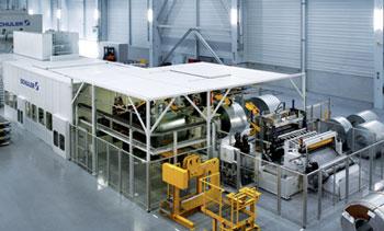
Figure 3: Servo-press blanking lines can maintain high rates of productivity, especially for high-strength material. The stroke slows during the clamping and cutting portion of the stroke, but can speed up when the tool isn’t touching metal.
But what if there were no blanking die?
That’s the idea behind laser blanking, a technology with years of research behind it that’s just now finding a home in the metal forming market (see Figure 4). Instead of a press, this coil-fed process uses lasers to cut blanks. No longer must stampers worry about breakthrough force and other challenges that come with hard tooling because with laser blanking, of course, there is no hard tool.
The laser blanking idea isn’t new. Flat-bed 2-D laser cutting machines have dominated the precision sheet metal fabrication arena for decades. But the process hasn’t yet become widespread in coil-fed operations. At first lasers were just too slow. But as lasers became more powerful, speed became less of an obstacle.
Advancements in solid-state fiber and disk lasers have breathed new life into the laser blanking concept. The beam is delivered from the power source to the cutting head with a simple delivery fiber. Moreover, the laser’s high brightness and 1-micron wavelength allow it to cut through thin sheet very quickly.
Thickness is a factor; laser cutting slows as thickness increases. But unlike a punch and die, the laser doesn’t care how hard or soft a material is. Class A (exposed) blanks in the automotive business usually are less than 3 mm thick, and thinner stock will become only more prevalent with industry’s push toward thinner, stronger material.
For maximum throughput, some laser blanking systems use multiple cutting laser heads. One configuration has one cutting head on the left side of the coil strip, another in the center, and one more on the right side. Each moves independently with and against the strip’s feed direction. And wherever the cutting heads move, a gap in the conveyor system underneath moves with them, providing space for molten material from the cut to fall (see Figure 1). The three lasers work together to increase cutting efficiency. To cut a shape, one laser can start where the other laser stops.
The strip moves not in stop-and-go fashion, but continuously forward. The entire process can occur on floor level—no massive presses requiring below-floor foundation work, and no under-floor scrap conveyor belts. Robots remove the finished blanks (see Figure 5), while the remaining scrap falls into large bins, which can be switched out as needed when switching between, say, aluminum and steel.
Using three lasers at once does increase processing speed. But now and in the foreseeable future, no laser is likely to outpace a blanking press, especially one that’s servo-driven. It comes down to the nature of the operation. A punch cuts an entire blank in one hit; a laser must trace every contour of every part profile.
This act of tracing, though, reveals several of laser blanking’s greatest strengths. The first is obvious: increased flexibility. If a stamping operation needs to change a blank profile, it simply changes the cutting program. There’s no need to change or build a tool.
Another strength involves contours. A traditional blanking tool is often angular, simply because it costs less to produce a die that cuts a simple shape. Hard tooling costs don’t apply to laser blanking, of course. Moreover, to cut an angle requires the laser cutting head to move straight, stop momentarily, and then move straight again. The laser actually moves more efficiently when cutting contours, because it never has to stop. And in many situations, blanks with curved edges make downstream forming operations easier and more reliable.
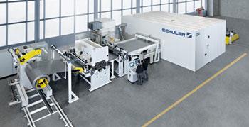
Figure 4: In this laser blanking line, the coil moves continuously.
Moreover, the process allows technicians to fine-tune blank contour shapes, which can ease downstream forming. This is especially beneficial in applications like hot stamping. Hot-stamped parts emerge from the press so hard that it becomes difficult or impractical to trim them mechanically. So they require a 3-D cutting laser to perform the trimming. With laser blanking, engineers can fine-tune the blank shape, which may (depending on the product) reduce the amount of subsequent 3-D laser cutting required.
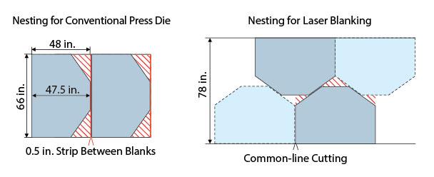
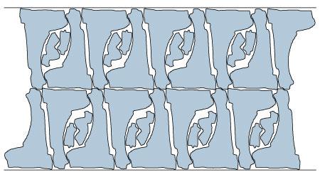
The most significant benefit of laser blanking may be material utilization (see Figure 6 and Figure 7). In fact, material is the greatest cost in any blanking operation. Complex, space-saving nests—with, say, certain parts nested within cutouts of other parts—were in some cases technically possible with a traditional blanking press, but the tooling costs could be prohibitively expensive. But again, with laser blanking, there is no hard tool.
In a traditional blanking line for a car door, the press blanks the door shape and window cutout and scraps the rest. In a laser blanking line, another part could be nested within that window cutout. Previously those two parts required two separate blanking lines. Now they are blanked in one. Yes, the speed of that one line is slower than a blanking press, but because the laser blanking line produces two parts instead of one, material costs are greatly decreased.
The technology also can help reduce the need for coil slitting. Previously a small or narrow part may have required a narrow strip. On the laser, that part can be blanked in a nest that fits well on a wider coil that doesn’t require slitting.
Choices in Blanking
Like any technology, laser blanking doesn’t make sense for every application. For high-volume operations that require extremely short cycle times, the servo-driven blanking press may be a good fit. And for other operations requiring simple blank shapes, a traditional cut-to-length line may suit best.
Regardless of what technology a stamping operation uses, though, one fact remains: When it comes to sheet metal forming, it all starts with the blank.
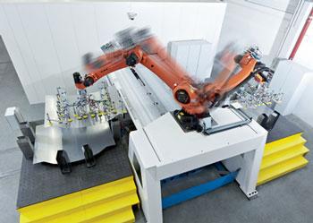
Figure 5: Robots pick and place two finished blanks into separate stacks. In this line, two parts, which previously were produced on two blanking lines, are now nested together and cut on one laser blanking line.
About the Publication

subscribe now

The Fabricator is North America's leading magazine for the metal forming and fabricating industry. The magazine delivers the news, technical articles, and case histories that enable fabricators to do their jobs more efficiently. The Fabricator has served the industry since 1970.
start your free subscription- Stay connected from anywhere

Easily access valuable industry resources now with full access to the digital edition of The Fabricator.

Easily access valuable industry resources now with full access to the digital edition of The Welder.

Easily access valuable industry resources now with full access to the digital edition of The Tube and Pipe Journal.

Easily access valuable industry resources now with full access to the digital edition of The Fabricator en Español.
- Podcasting

In this episode of The Fabricator Podcast, Caleb Chamberlain, co-founder and CEO of OSH Cut, discusses his company’s...


