


Manager, Advanced Technology
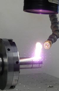
An Nd:YAG laser performs seam welding of steel tube components.
This article is adapted in part from Mark Rodighiero, "Putting It Together: Laser Welding Systems," presented at FABTECH® Intl. & AWS Welding Show, Nov. 11-14, 2007, Chicago, ©2007 by the Fabricators & Manufacturers Association Intl., Society of Manufacturing Engineers, and the American Welding Society.
No longer a novelty, laser beam welding has a long history as an efficient joining method. Today the process represents another tool in the manufacturer's toolbox, and as U.S. industry continues to leverage the laser's unique welding characteristics and flexible implementation, it has gradually found a home on more production floors.
The joining method has evolved into a proven process, and like any proven manufacturing process, it should be matched with the application with the best-suited material and geometry. And the earlier this match happens—be it during preproduction or, ideally, product design—the better. In other words, if a company designs for the laser welding process, it will reap the benefits.
Most laser processes weld autogenously, meaning without filler metal, with a minimal heat-affected zone (HAZ) and just enough heat to melt and fuse the material. This produces a high-quality weld joint with minimal thermal distortion. But welding autogenously does require intimate contact between the mating surfaces. Because the laser is a highly concentrated heat source, the joint generally melts, fuses, and cools extremely quickly. This means the process must work with material that can endure quick cooling without causing weld defects, such as cracking.
Adopting a laser welding process involves four principal considerations:
1. Is the process viable for the application, able to produce welds that meet criteria, be it a specific pull strength, homogeny, or visual appearance, based on the part material, geometry and fit-up tolerances?
2. Which laser equipment is best-suited for the application? For this, the application's throughput, weld path, beam delivery, and penetration requirements can be deciding factors.
3. What workstation will the application require, how will the part be held, and does it or the laser need to be manipulated? Will an X-Y system be adequate, or will it require Z, or rotary, motion? Regarding tooling, will one or multiple parts be held at a time? What kind of enclosure will the workstation have to house the process safely? For unloading and loading, will doors be manual or automatic? Does the workstation have a fully interlocked, light-tight enclosure that follows ANSI guidelines (Z126.1), including proper machine safety labels?
4. How will the system and process be verified, monitored, and supported during implementation?
The keystone to it all is choosing the right materials and bringing them in consistent contact, time after time. After this is accomplished, choosing all other process variables—laser type and delivery, tooling, the workstation, and so on—becomes straightforward.
Figure 4 Modeling tooling with software (left) can significantly accelerate the process toward the final fixture design.
 Figure 1
A laser produces a thin weld with a small HAZ, but the material must be able to endure quick cooling. The rapid thermal cycling of laser welding can create problems if certain elements are present—elements that solidify at different melting points or form brittle structures within the weld and HAZ microstructure. Microseconds after the laser weld, certain elements may solidify earlier, migrate toward the grain boundary, result in brittleness, and, ultimately, cause cracking during rapid cooling or even after cooling.
Four elements are worth watching when selecting material: carbon, phosphorus, sulfur, and manganese. Typically, a material should have 0.12 percent carbon or less. A company may have to choose from 303, 304L, or 316. Many may choose 303 because of its free machining characteristics, but its high carbon content (0.15 percent) and high levels of sulfur cause problems for laser welding. A better choice might be 304, 314L, or a 316 stainless. In stainless material, such as the 304 and 316 series, the chromium-nickel ratio generally should exceed 1.7. For carbon steels, another key relationship is the ratio of manganese to sulfur. Manganese alleviates the effects of sulfur to produce FeS, an embrittling compound. Typically, the Mn-to-S ratio should be greater than 10.
For aluminum, the rules become a little blurred because of a large range of alloys and alloying elements. If possible, an alloy should be selected with minimal alloying elements. Otherwise, welding trials can be used to prove process viability.
 Figure 2
Laser welding can work with three kinds of joints—lap, butt, and fillet—and each has its pros and cons.
The butt joint provides the most efficient way to join two base metals, because the energy is focused directly down the joint line. But part fit-up can be especially critical.
The two workpieces must be physically touching (butted together within a tolerance of less than 100 microns, depending on thickness), the material edges must be clean with minimal warping and distortion, and the beam must precisely track along the joint line.
Lap welds are the most forgiving tolerancewise, because the joint area is effectively as large as the joint width itself. As long as the laser welds within that width, fusion will occur. But such an orientation can be inefficient, because the laser expends energy penetrating the top layer to get to the joint line.
A fillet weld is a happy medium, having a little more tolerance forgiveness than the butt joint, but not as much as a lap geometry, with welding efficiency somewhere in between the two.
Typically, the laser has an optical spot size of about 0.02 inch in diameter; therefore, accuracy in part alignment and beam tracking along the joint must match up to this, with a usual tolerance being between 10 and 15 percent of the beam diameter. Most conventional laser welding applications—especially those for thin gauges—use fillet and lap configurations, which facilitate ease of tooling and relatively forgiving tolerances.
For most, the process choice often comes down to three laser sources: CO2, fiber, or pulsed Nd:YAG. Both CO2 and the more recently developed fiber lasers are suited for penetration seam welding (greater than 0.04 in. thick), although a fiber can be used for some microapplications. In terms of welding performance, the CO2 laser is the most cost-effective source to penetrate thick gauges, particularly steels. Although a fiber laser is more expensive per watt, it offers the advantage of fiber delivery for ease of integration, reduced running costs, and improved welding of aluminum.
Both laser sources can penetrate thick plate and perform keyhole welding faster than any other process. Therefore, the selection depends on the application. For instance, a simple rotary weld will favor the CO2, but a robotic or multiaxis welding station favors the fiber. CO2 lasers still dominate high-speed thick- and thin-gauge applications, but because of their simplicity and ease of maintenance, fiber lasers may be applied to more welding applications in the years to come.
CO2 and fiber lasers weld with average power; a 5-kW laser outputs 5 kW. A pulsed Nd:YAG, on the other hand, can provide up to a 10-kW pulse from a 500-W laser. The ability to precisely control the peak power, pulse duration, and pulse shape makes the Nd:YAG laser efficient for spot welding and minimal-heat-input seam welding.
It's those pulses in Nd:YAG that do most of the work, allowing lasers with very low average power to penetrate metal. For instance, a 25-W Nd:YAG can penetrate 0.030-in. steel and aluminum, thanks to the relatively high peak power. The same application would require at least a 1-kW continuous-wave (CW) CO2 or fiber laser to achieve such penetration, particularly for the aluminum.
Nd:YAG's downside has been its inefficiency. The flash lamp emits various wavelengths with each pulse, but only some of those wavelengths make it to the rod, the laser's source; the rest dissipates as heat. This means power efficiency hovers around 3 percent to 4 percent, compared with CO2's 10 percent to 12 percent, and 25 percent for a fiber laser.
Still, for fine, small seam welding—like those in the electronics and medical industries—Nd:YAG has remained the process of choice because it requires only very low average power to weld, with less heat input, and with a beam quality that has consistently improved over the years.
How easily the base metal is held in place for welding can dictate which laser process ultimately makes its way to the shop floor. A part might be more efficiently welded with a CO2 laser on the basis of welding speed alone. But part geometry, setup, and fixturing should enter the equation as well. With a CO2 system (see Figure 1), mirrors must be properly aligned, as well as the beam expander and telescopic elements between those mirrors.
Nd:YAG and fiber lasers offer flexible beam delivery through a fiber, as opposed to hard optics (see Figure 2). The initial setup requires only bolting an end effector onto a focus head; the laser itself may be positioned anywhere within the workstation. An Nd:YAG laser also can offer "time share" or "energy share" characteristics (see Figure 3). With several independently controlled fibers connected to a single laser source, the system can either distribute the laser's full energy to different workstations at different times, or can divide the total energy among the workstations for simultaneous use. (CO2 lasers also have this capability, but this again can involve some complications when engineering the hard optics.)
Within the workstation, tooling can make or break the whole system. If it can't be held, it can't be welded. Certain industries, like medical and electronics, must produce intricate parts, and those parts must have areas where they can be held securely without blocking the laser focusing head, the focusing laser itself, or the shielding gas. How is the part going to be put into the workstation? Is it going to use fixed tooling, magnetic-based clamping, quick-release tooling? Considering the tooling in detail can eliminate major issues down the road.
In the system design process, modeling software is an invaluable tool (see Figure 4) to ensure every aspect of design is considered and nothing is overlooked. Many times it's the simple things, such as beam clearance or gas access to the weld, that are missed. The software accelerates the process and, at the same time, acts as a safety net. However, nothing beats having real parts in hand with live tests and prove-outs of laser welding. At this stage the process becomes iterative, involving fine-tuning of the original concepts.
Communication between all parties is the foundation of an on-time and successful system design, delivery, and installation. It is essential that project engineers from the end user and the vendor remain in regular contact to ensure changes can be accommodated quickly and problems resolved, so that at the final buy-off there are no surprises.
Laser systems can have some self-monitoring capabilities. Typically, all lasers have internal power feedback to ensure the delivered power matches the demanded power, and external power meters verify the power after the final focus optic. Many laser welding monitors also show basic information regarding process drift, but are unable to detect enough information to determine whether or not a weld is good. Other systems offer remote diagnostics, so off-site technicians can access the machine and perform troubleshooting. Regardless of the monitoring method, though, the best process verification involves using a benchmarked weld showing width and penetration for a certain weld schedule.
All stages of a laser welding implementation should be marked by a close working relationship between all parties. Companies should never implement a laser process without knowing that full and proper technical support is available, either in-house or from the contracted supplier.
The bottom line: No matter how well implementation goes, problems can arise, and technical expertise should be on hand to help.
Weighing the Considerations
In implementing a laser system, no single factor—material type, joint and part geometry, laser process, workstation, verification, and support—exists in a vacuum. For instance, even if material selection is less than ideal, joint geometry and process requirements may prove the laser is still the best solution. An application involving a material that is considered difficult to weld, say, 430 stainless steel, could work with a small joint geometry, despite its high carbon content (above 0.12 percent). The small-seam application may involve so little heat, focused in such a small area, that cracking or postweld heat treatment could be avoided.
As another example, consider a company looking to make an extremely high-quality butt-joint weld. The material type and thickness could point the application toward either an Nd:YAG or fiber laser, and engineers may at first choose the fiber laser. However, because the laser welds using average power, the process's spot size required to provide sufficient power density may need to be extremely small, perhaps 50 to 100 microns. Such a thin beam makes tooling a big challenge, and tracking the joint line becomes critical. How will the company hold the part so that the beam hits in the right place every time? Here, engineers may choose to go instead with an Nd:YAG with a spot size of more than 200 microns. Is the welding itself as fast as the fiber laser? Maybe not, but welding speed means nothing if the part can't be held in place accurately and consistently under the laser.
In the end, it's about weighing quality and cost requirements, and designing the part to suit the process. With material and joint geometry requirements set, most of the remaining factors usually fall into place.

The Fabricator is North America's leading magazine for the metal forming and fabricating industry. The magazine delivers the news, technical articles, and case histories that enable fabricators to do their jobs more efficiently. The Fabricator has served the industry since 1970.
start your free subscription
Easily access valuable industry resources now with full access to the digital edition of The Fabricator.

Easily access valuable industry resources now with full access to the digital edition of The Welder.

Easily access valuable industry resources now with full access to the digital edition of The Tube and Pipe Journal.

Easily access valuable industry resources now with full access to the digital edition of The Fabricator en Español.
In this episode of The Fabricator Podcast, Caleb Chamberlain, co-founder and CEO of OSH Cut, discusses his company’s...


