


Roll form tooling design for air bending
Selecting a techique for reduced distortion
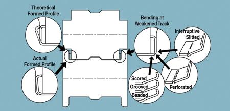
Figure 1Scoring, grooving, beading, perforating, and interruptive slitting are techniques that can reduce distortion in air bending.
When a bend is formed with the air bending process (air bend), the interior of the bending corner can't be reached by either the top roll or the bottom roll, making it difficult to control the part's profile and dimensions. Figure 1 illustrates a typical air bend. The theoretical formed profile is the desired profile. The actual formed profile is the finished part, which was distorted because the top roll couldn't reach the interior corner to hold it in position. The bottom roll flange lifted the section and distorted the profile. Several techniques can reduce such distortion in parts formed by air bending.
The Small-radius Forming Technique
Forming a radius smaller than the metal thickness is a suitable technique for the air bend in Figure 1. Scoring, grooving, beading, perforating, or interruptive slitting weakens the bending track. Scoring is the most commonly used technique. The score depth should not be deeper than one-third the metal thickness in cold roll forming applications. If the score is deeper than one-third the metal thickness, the metal may break at the scored track. In hot roll forming, a grooving track is easy to form and prevents corner cracking.
The beading technique is suitable for thin metal applications. Beading doesn't break the protective coating and doesn't reduce the thickness at the bent section.
A rotary punch performs perforating or interruptive slitting.
The False-bend Technique
The false-bend technique exposes the blind bend (the air bend) to the top roll or bottom roll by curving a straight section (see Figure 2). After the section is curved, the top roll can physically reach the interior bend and form it to 90 degrees precisely. The station after the false-bend station flattens the curve. Usually the false-bend design needs an additional station.
The Vertical Side Roll Technique
The vertical side roll located at the outside of the bend is the outer side roll. The forming force from the outer side roll has the same direction as the bending action. It forms a better-quality bend than the conventional rolls in Figure 1. The vertical side roll located at the inside of the bend is the inner side roll. The function of the inner side roll is forming the desired radius at the bend.
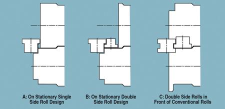
The single roll design in Figure 3Acannot control the radius dimension because tooling cannot reach the inner corner. The double side roll design in Figure 3Bforms the profile and the dimension more accurately than the roll design in 3A.
The side rolls, which are mounted in the same central line plane as the conventional rolls, are called stationary side rolls, as shown in Figure 3A and Figure 3B. The stationary side rolls and conventional rolls form a rotational extrusion head that squeezes the formed section from all directions: up, down, left, and right. This extrusion process provides strict control over the profile and dimension.
Single side rolls and double side rolls can be mounted before the conventional roll station (see Figure 3C). This arrangement allows more space for large side rolls.
The Angle Side Roll Technique
The inner angle side roll can contact the inner bend on both the vertical and horizontal surfaces to form a small and accurate bending radius. The single side roll in Figure 4Ais referenced to the bottom roll. Two-angle side rolls are shown in Figure 4B. The concave top roll in Figure 4Cprovides more forming contact surface, if needed.
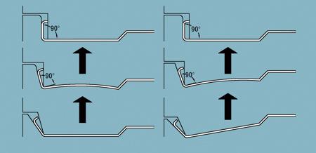
Figure 2Two examples of the false-bend technique show how the bottom section is curved to allow the top roll to make the 90-degree angle at the left side of the part.
The double angle side rolls can be mounted before the conventional roll station, as shown in Figure 4D. This is similar to Figure 3C in that it provides more space for large side rolls.
Stationary Mandrel
In many cases an air bend can be accomplished effectively with a stationary solid mandrel mounted in a conventional roll (see Figure 5). It combines both the roll and mandrel features. The roller and mandrel are attached to the roll stand. The roller is captive. The hole on the mandrel is more than a half circle, which keeps it in place horizontally, and the set screw prevents the roller from escaping vertically.
Hanhui Li is senior engineer with Worthington Armstrong Venture (WAVE), 9 Old Lincoln Highway, Suite 200, Malvern, PA 19355, 610-722-1232, hanhui_li@armstrong.com.
Reference
George T. Halmos, Roll Forming Handbook (Toronto: Taylor & Francis Group, 2006).
About the Author
About the Publication
subscribe now

The Fabricator is North America's leading magazine for the metal forming and fabricating industry. The magazine delivers the news, technical articles, and case histories that enable fabricators to do their jobs more efficiently. The Fabricator has served the industry since 1970.
start your free subscription- Stay connected from anywhere

Easily access valuable industry resources now with full access to the digital edition of The Fabricator.

Easily access valuable industry resources now with full access to the digital edition of The Welder.

Easily access valuable industry resources now with full access to the digital edition of The Tube and Pipe Journal.

Easily access valuable industry resources now with full access to the digital edition of The Fabricator en Español.
- Podcasting

In this episode of The Fabricator Podcast, Caleb Chamberlain, co-founder and CEO of OSH Cut, discusses his company’s...
- Trending Articles
1
How to set a press brake backgauge manually

2
Capturing, recording equipment inspection data for FMEA

3
Tips for creating sheet metal tubes with perforations

4
Are two heads better than one in fiber laser cutting?

5
Hypertherm Associates implements Rapyuta Robotics AMRs in warehouse
