


Contributing Writer
 |
Of all the materials that can be cut on industrial band saw machines, structural steels—such as pipe and tubing, plate, angle and channel iron, and I beams—are among the most common and challenging.
The challenges often arise when a blade encounters changes in the cross section while cutting structural parts, alone or in bundles. These intermittent and sudden changes increase vibration and part movement.
You can choose saw blade features that address the problems inherent in cutting this type of material.
The most important aspect of choosing the correct blade for any cutting application is tooth size.
When cutting a solid shape, such as round or square solid bar, it is easy to determine the most efficient tooth size to produce the correct chip load for efficient material removal. These shapes have a relatively constant cross section, and the blade is well-supported throughout the cut.
With structural shapes, however, as the blade passes through the material, the area of material engaged by the saw teeth changes radically.
For instance, when you lower a column-feed horizontal saw head onto a square tube, the teeth engage a relatively long, solid cross section on the top of the tube. As the blade penetrates, it breaks through the top wall and drops into the hollow part of the tube. The cross section is significantly reduced as the blade feeds through the parallel sidewalls. At the bottom of the cut, the blade again engages a large section through the bottom wall of the tube. The tooth size that cuts the large section efficiently does not cut the thin sections efficiently, and vice versa.
When considering the tooth size to use for a radically changing cross section, remember that you can alter operating conditions to allow a large tooth to cut efficiently in a small section, but you cannot alter operating conditions to allow a small tooth to cut efficiently in a large section.
You can cut a thin-walled structure with a large tooth without damaging the blade simply by reducing the feed or drop rate of the saw head. When properly adjusted, the teeth still can pull the proper chip load on each point.
However, if the tooth is too small for the section being cut, for example, a 10/14 variable-pitch tooth cutting a 6-inch solid section, there are no changes in operating conditions that will allow the tooth to cut properly. Even if the feed rate is set so that a proper chip load is achieved, the gullet capacity between the tooth points is too small to accumulate and carry the chips out of the cut.
When the gullets become completely clogged with chips, the blade cannot penetrate the work, or the chips work out to the sides of the blade. Both of these conditions are extremely harmful to the blade. By penetrating the work improperly, the tooth points become dull quickly because of excess friction and heat. When chips work out of the gullets along the side of the blade, the blade may begin to jump or bounce, resulting in tooth strippage.
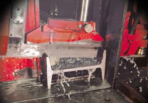 |
| Figure 1: When cutting an I beam, orienting it in the shape of an H produces a more consistent cross section. |
Correct part orientation is the simplest way to make the cross section more consistent.
For example, on a horizontal saw, you should orient angle iron as an inverted V shape rather than an L shape. When oriented as an L, the blade must cut through a very thin single leg for part of the cut and a very wide section for the other leg. Oriented as a V, the blade cuts through both legs at the same time, and the cross section remains more consistent throughout the cut.
When cutting a square tube, if you put a small wedge under the tube to angle it slightly, the cross section becomes more consistent. This technique also works well with plate when it is too wide to stand on end.
When cutting an I beam on a scissor-feed horizontal saw, you can orient it in the shape of an I or an H. The H orientation produces a more consistent cross section (see Figure 1).
In general, when structural shapes can be bundled or nested together, the cross section improves (see Figure 2). Angle iron, for example, produces a nearly solid cross section when bundled. Channel iron produces a denser, more consistent cross section when bundled or nested.
Some saws, called canted-head machines, are designed for cutting structures. On a column-feed horizontal machine with a canted head, the machine head is mounted on twin posts at a slight angle. This produces the same effect as orienting the part at an angle. With the head mounted at an angle, the blade passes through both the top and bottom surfaces of the structure at an angle, thus greatly improving the cross-sectional consistency of the cut.
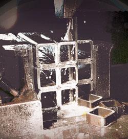 |
| Figure 2: In general, when structural shapes can be bundled or nested together, the cross section improves. |
Band saw feed rates are determined by the machinability of the material being cut. This usually is expressed in square inches per minute as the removal rate.
Most blade manufacturers provide charts that give removal rates for the majority of materials cut on band saws. Few, however, include standard A-36 carbon steel, one of the most commonly cut materials, because of its erratic machining properties. A reasonable average removal rate for A-36 carbon steel is 8 to10 square inches per minute.
To calculate the required feed rate for cutting structurals, take the following three steps:
Part movement within bundles is a serious problem for band saw blades. Bundles of round tube can produce "spinners" – bars that are not securely held within the bundle. Spinners invariably will destroy any blade used.
Bundles of material, regardless of the shape, must be vised securely — preferably from all sides — to prevent movement within the pack. Most production-type band saw machines have top hold-downs or bundle-vising options.
A similar movement problem often is encountered when cutting single pieces of certain shapes. I beams are particularly notorious for this.
When I-beams are manufactured, they are highly stressed by their manufacturing processes. When they are subsequently saw-cut — especially larger I beams with web widths in excess of 10 or 12 inches — these stresses are relieved by the act of saw cutting, and the part tends to twist, often pinching the band saw blade in the cut.
Heavy set blades with an extra tooth set to create a wider kerf are available for these types of cutting applications.
Structurals present some unique challenges to professional cutting operations. Changing cross sections, erratic machining properties, and increased vibration all conspire to cause premature blade wear. However, proper attention to tooth selection, feed rates, and orientation of the part to the blade can greatly improve blade durability and cutting rates.


The Fabricator is North America's leading magazine for the metal forming and fabricating industry. The magazine delivers the news, technical articles, and case histories that enable fabricators to do their jobs more efficiently. The Fabricator has served the industry since 1970.
start your free subscription
Easily access valuable industry resources now with full access to the digital edition of The Fabricator.

Easily access valuable industry resources now with full access to the digital edition of The Welder.

Easily access valuable industry resources now with full access to the digital edition of The Tube and Pipe Journal.

Easily access valuable industry resources now with full access to the digital edition of The Fabricator en Español.
In this episode of The Fabricator Podcast, Caleb Chamberlain, co-founder and CEO of OSH Cut, discusses his company’s...


