


Why buy new tooling for a sheet metal hand brake?
A punch nose with a radius makes bending predictable
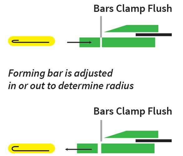
Figure 1
To adjust the forming radius on a hand brake, such as
the HVAC style shown, narrow or widen the distance between
the tool and the forming bar.
Q: I was in one of your training classes awhile back where you discussed the proper use of the hand brake. During your presentation you stated that the inside bend radius changes as the relationship between the forming bar and the nose of the punch [tooling] changes. You told us that this was true when you are using a precision box, leaf, or pan brake, or the heating, ventilation, and air conditioning (HVAC) version of the same machine. When I returned to my shop and tested that theory, I found it to be true within the limits of the machine adjustments.
You also stated that machine manufacturers always recommend that the distance between the forming bar and the punch nose should be set to a material thickness or slightly less. This produces a radius somewhere close to the material thickness, at least in mild cold-rolled steel. This I also found to be true.
The question I have for you is this: If I can change within reason the inside radius simply by adjusting the tool and forming bar relationship, why would I want to purchase tooling with nose radii other than the normal 1⁄32- (0.032-inch /1-mm) radius punch that came with the machine? For the record, I work at a two-person operation that manufactures very small quantities of precision parts, and I struggle daily with forming on this machine.
A: The hand brake you refer to is also known as a finger brake, box brake, or pan brake, and of these there are two types: the precision style and the HVAC machine. Both are the same basic machine but have some big differences. Nonetheless, both styles are designed to produce parts using a clearance of one material thickness between the forming bar and the nose of the tool.
As you narrow or widen the measured distance between the tool and the forming bar, the inside radius will change. If you were using an HVAC machine, you would make that adjustment by moving the forming bar in and out, as the nose of the tool and the edge of the platen—the machined surface the material is clamped on—are fixed in position (see Figure 1). These machines tend to be limited to 18 ga. (0.047 in.) and 20 ga. (0.036 in.), as ductwork is rarely made from heavier or thicker materials.
The precision version of the hand brake is adjusted in the opposite manner. On these machines, the relationship between the platen and the forming bar is fixed, and the tooling mounted into the clamping beam is the adjustable part of the machine.
This leads me to the answer to your question—it’s all actually a little deeper than you might think. To begin with, the original tooling included with these brakes generally is not a true 1⁄32-in. radius. Rather, there is a small flat on the nose of the tool. This is because these types of machines are for light-gauge use.
The one you described is a small tabletop model. These machines are designed for materials 16 ga. (0.059 in.) or less, whereas the typical HVAC machines are set pretty much for 18 ga. (0.047 in.).
The reason that you would purchase tooling with a radius, rather than just use the tools that came with the machine and adjusting for the radius, is twofold. First, once you move away from that one-material-thickness recommended clearance, the bend begins to distort. Rather than producing a true radius, the hand brake bends the area of the material being clamped in advance of the actual bend (see Figure 2). This happens because the material is being clamped too far away from the forming bar, causing it to begin to pull away from the platen.
The second reason to purchase tooling with a radius is that, by using a punch or tool with a larger radius on the nose, you can cleanly produce large radii, such as 1⁄8 or 3⁄32 in., without that leading distortion. By using a large-radius tool, you should be able to achieve a radius that’s true to form. This means you will have a valid bend deduction, or the amount of material to be removed from the flat dimensions to account for elongation caused by bending the sheet metal. Remember, the flat part is always less than the sum total of the outside dimensions of the part.
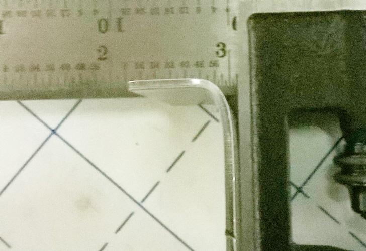
Figure 2
This bend, formed on a hand brake, distorted because
the material was clamped too far away from the forming
bar, causing it to begin to pull away from the platen.
Here are a few tips that could help relieve some of the struggles you are having. Note that I don’t know which style or brand of machine you are using, and one machine can be very different from another. The tips that follow assume that you have a machine in which the clamping bar and tooling are adjustable.
You need to review various factors and adjustments to ensure quality in your project. First is the relationship between the nose of the tool and the forming bar. Some machines are fixed and some are adjustable. This means they can get out of parallel with the forming bar. Check the tooling and the area where the tooling mounts for burrs, dings, and distortions that would keep tools from mounting correctly and securely into the clamping bar.
Once you have the tooling installed, correct any error by adjusting the tooling. You need to make this adjustment on both sides of the frame assembly. First, place two pieces of tooling at both ends of the clamping bar. Then, use your square or calipers to ensure the measured distance from the edge of the platen or forming bar to the nose of the tool is the same on both sides of the machine. There should be no taper. This method ensures that the backgauge is square to the forming bar.
Note that on some machines the backgauge is nothing more than a piece of 18-ga. sheet metal running the length of the clamping bar; others have multiple fingers across the width. These generally are not adjustable as individual stops. Either way, gauge adjustments are difficult. If yours has the 18-ga. sheet backgauge, ensure that there are no burrs or damaged areas along the length of the gauge. You can dress it with a file, if necessary.
If yours has the finger-style gauges, make sure that those backgauge stops are square to the forming bar and tooling. If you don’t, you may find that in one area the measurements are fine because you are gauging from the flat surface on the face of the gauge. If the gauge finger is not parallel to the forming bar, you might be gauging from a high point or corner edge of the gauge.
There are a couple of ways to find a good starting point for gauging. The first is to set the gauges by lining up your part with the inside mold line. Line up the inside mold line with the nose of the tool, clamp, and then set your backgauges against the part.
You also can use your calipers to measure from the nose of the tool to the backgauge. This can be done accurately by clamping a piece of material that is thicker than the gauge, allowing the tool nose to be parallel to the platen while still allowing the gauges to be moved into position.
Be advised that, even under the best of conditions, you will need to run several test pieces and make the necessary adjustments to form a correct part.
Gear lash can also be a problem. Make sure that you move the backgauge(s) away from the tooling farther than required and then back into position. This helps account for any error in the adjustment linkage.
Next, set the bend angle and springback allowance. Adjust this using a spinning collar or by moving pins from hole to hole in 15-degree increments; you then can make finer adjustments by turning a machine screw in or out, which moves the stopping dog in or out to adjust the angle.
By placing the pin in the desired hole and fine-tuning, you can achieve an accurate bend every time. The single-collar style is a little harder to adjust and allows only one stop setting at a time.
One final note: It is best practice to bend several test pieces before the brake is set up. The test bend will reveal the true measurable radius, help you set the angle, and, therefore, make the correct bend deduction possible to predict.
Steve Benson is a member and former chair of the Precision Sheet Metal Technology Council of the Fabricators & Manufacturers Association International®. He is the president of ASMA LLC, 2952 Doaks Ferry Road N.W., Salem, OR 97301, steve@theartofpressbrake.com. Benson also conducts FMA’s Precision Press Brake Certificate Program, which is held at locations across the country. For more information, visit www.fmanet.org/training, or call 888-394-4362. For more information on bending, check out Benson’s new book, The Art of Press Brake: The Digital Handbook for Precision Sheet Metal Fabrication, © 2014, available at www.theartofpressbrake.com.
About the Author

About the Publication

subscribe now

The Fabricator is North America's leading magazine for the metal forming and fabricating industry. The magazine delivers the news, technical articles, and case histories that enable fabricators to do their jobs more efficiently. The Fabricator has served the industry since 1970.
start your free subscription- Stay connected from anywhere

Easily access valuable industry resources now with full access to the digital edition of The Fabricator.

Easily access valuable industry resources now with full access to the digital edition of The Welder.

Easily access valuable industry resources now with full access to the digital edition of The Tube and Pipe Journal.

Easily access valuable industry resources now with full access to the digital edition of The Fabricator en Español.
- Podcasting

In this episode of The Fabricator Podcast, Caleb Chamberlain, co-founder and CEO of OSH Cut, discusses his company’s...
- Trending Articles
1
How to set a press brake backgauge manually

2
Capturing, recording equipment inspection data for FMEA

3
Tips for creating sheet metal tubes with perforations

4
Are two heads better than one in fiber laser cutting?

5
Hypertherm Associates implements Rapyuta Robotics AMRs in warehouse
