


Contributing Writer
Editor's Note: This article is an edited version of an article that was published in the September 2005 issue The FABRICATOR®.
As some stamping manufacturing has moved overseas, the U.S. slitting market has become saddled with overcapacity. Stampers can improve coil processing efficiencies by upgrading the equipment they use in the following areas: entry coil storage, coil inside diameter (ID) changes, and slitter tooling changeovers; scrap handling; and strip tensioning.
A good entry coil storage system can improve efficiency by reducing line downtime and by allowing efficient use of overhead cranes. The ability to stage multiple coils is crucial because it prevents waiting at the line, and it allows the crane operator to retrieve and load coils whenever it is convenient, not when it is necessary. Common coil storage devices are turnstiles, saddles, and turntables.
Turnstiles with four arms are suitable for many slitting line applications. Because they rotate, they allow the line operator to select any coil in any order. However, they support coils by the ID, and may damage thin, heavy coils. Also, it can be difficult to load small-ID coil.
Storage saddles (see Figure 1) support coils from their outside diameter (OD). This design eliminates ID damage on heavy coils and allows easy loading from an overhead crane. The drawback is that saddles usually are placed in a straight line, which requires the operator to select the coils in consecutive order.
Storage turntables have the advantages of turnstiles and saddles. A storage turntable is composed of saddles, so it eliminates the risk of ID damage. The saddles are mounted on a turntable, so the operator can select the coils in any order. This design usually requires a pit-type coil-loading car or a very low-profile scissor lift car.
Expanding-mandrel uncoilers have a limited expansion range, meaning they might handle coils from 16 inches to 20 in. or from 20 in. to 24 in. ID without filler plates. If the operator needs to run coils with a larger ID than the uncoiler was designed to handle, some type of filler plate is required. Loading and removing these filler plates can cause quite a bit of downtime. Two very different designs are available, but their efficiency depends on how frequently they are used.
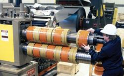
Filler rings, sometimes called doughnuts, are an inexpensive way to run larger-ID coils (see Figure 2). They have no range, meaning they can handle a single size only, such as a 29-in.- ID coil. Rings are best for occasional use only because, even though they can be loaded fairly quickly, they have to be loaded into each and every coil run.
Bolt-on filler plates can be time-consuming to load, but for multiple coil runs they tend to be more efficient because they stay on the drum and do not need to be loaded into each coil. They also provide the same expansion range as the base drum, which means they could be designed to handle 28-in.- to 32-in.-ID coils, for example, on a 20-in. to 24-in. drum. The plates can be made from plastic for ease of handling or from steel for durability. Newer designs include a speed-loading fixture and use tabs instead of bolts. This type of design allows the plates to be mounted on an uncoiler in fewer than five minutes.
Operating a line efficiently for just-in-time manufacturing requires quick-change slitter heads. Having more than one head allows the operator to change the tooling offline while the machine is running. Several methods for changing heads are available, with cost, floor space, and crane time being primary considerations.
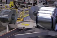
Figure 1Using storage saddles for staging heavy coils eliminates ID damage.
Removable-head slitters that lift off by crane are the least expensive approach to offline tooling changeover (see Figure 3). This method is time-consuming, though, because personnel must remove mechanical fasteners, and the crane might not be available immediately. Operators must use extreme care—a removable head is a heavy piece of machinery, so this activity has some risk.
Injector-head slitters that shuttle in and out of the line on rails are more expensive, but operators can change them safely in as little as two minutes. This design requires a fair amount of space and may block the operator's view of the line.
Slitter knife transfer units hold the tooling offline on rotating arms and use a mechanical pusher to slide the tooling onto the arbors. This design, which resurfaced recently, was patented in 1970 and was intended to speed tooling changes on fixed-head slitters. The main drawback is that the tooling can bind up during transfer.
Another design known as a turret-head slitter (see Figure 4) evolved from the original knife transfer unit and allows safe, two-minute head changes at a reasonable cost. No space is required on the operator side of the line, and the design provides easy, ergonomic access to the slitter tooling.
If handled poorly, scrap edge trim can cause excessive downtime in slitting lines. Three major systems exist for handling scrap. The efficiency of each type is determined for the most part by the coil thickness range the line will run.
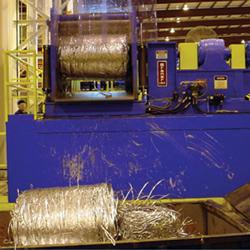
With a scrap baller system, the slitter head drives the edge trim into an accumulation pit. Later, usually after the coil has finished running and the line has actually stopped, the scrap baller pulls the edge trim from the pit under zero tension and uses a steel mashing roll to force it into a compact ball (seeFigure 5). This design is most efficient for material from 0.005 in. to 0.187 in. thick because zero tension means fewer scrap breaks, and the operator is not distracted by scrap during line run. To operate properly, scrap ballers do require a fairly large accumulation pit.
Scrap winders pull the scrap under tension from the slitter head while the line is running. It is advantageous to install them in pairs to maintain uniform tension on each scrap strand. This design works for material from 0.010 in. to 0.500 in. thick, but is best-suited for medium gauges up to 0.250 in. thick because light-gauge scrap has a tendency to break and heavy-gauge scrap is difficult to thread. The line operator must pay attention to the scrap and maintain tension at each winder during line run.
Scrap choppers are located directly after the slitter head and have custom tubes or chutes that allow self-threading. Scrap choppers can accommodate material from 0.010 in. to 0.750 in. thick, but are best-suited for heavier gauges because frequent knife maintenance may be required when cutting thin material. This is the most expensive type of scrap handling system, but the higher value of the chopped scrap may help justify the cost.
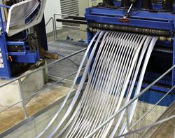
To ensure proper tracking in a rolling mill, flat-rolled coils are produced with a crown—the center of the strip is thicker than the edges. Therefore, when a coil is slit, the thicker mults in the center rewind to a larger diameter than the thinner mults at the edges.
Years ago slitting lines ran only in tight-line mode. To wind each slit coil tightly, the operator would have to stuff pieces of paper or cardboard into the thinner mults to make them the same diameter as the thicker mults. This mode of operation was not only dangerous, but it also induced camber in the outside mults because they were fanned out at an angle for separation after slitting and then bent straight under tension at the recoiler drum.
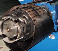
Figure 2Filler rings allow an uncoiler to handle large-ID coils safely.
The addition of a looping pit and tension stand into slitting lines is still one of the greatest advances in coil technology (see Figure 6). Loop slit operation allows the line to produce tight coils and straight side walls without the danger of stuffing cardboard and without the quality issues resulting from camber induced during tight-line operation. The real trick to loop slitting is to apply the required amount of back tension without damaging the strip—and without spending a fortune on tension stand consumables and maintenance. Several tensioning methods exist, but the most appropriate machine depends on the type of material run.
Pad-type tension stands use felt-covered boards to apply tension to the strip. An air bladder can be used, but a series of cylinders applies the clamping pressure more evenly across the boards. These machines are simple in design, so they are among the least expensive to purchase, and the felt is relatively inexpensive. Using a Velcro®-type attachment system allows quick changes, and a large board size reduces strip damage by spreading the clamping force over a large area.
Rotary tension stands use rolls to apply tension to the strip. Because the rolls rotate at approximately the same speed as the strip, rotary tension stands reduce scratching and usually are preferred for surface-critical material.
Cylinders or screw jacks clamp the rolls, and the braking force can come from a water-cooled brake or an electric drag generator. Polyurethane rolls work well on dry strip, and nonwoven fabric rolls work well on oily strip. Roll changes can be accomplished quickly with lift-off cartridges, but newer duplex designs save space and allow roll changes in as little as two minutes.
In another concept for tensioning, a roller leveler elongates, or stretches, some of the slit mults to reduce the apparent strip length differential and, therefore, reduce the need for a looping pit.
This method can be effective for slitting lines that would require a shallow looping pit, but stretching the mult also reduces its width, a phenomenon known as necking. Necking becomes more severe as the pit requirement becomes deeper because more stretching has to occur. In some cases, the mult width can be reduced by 0.040 in. or more. In theory, machine operators can adjust the tooling on the slitter to compensate for the width reduction, but this assumes that the amount of strip crown is known and the strip crown is consistent throughout the coil.
The actual depth of the looping pit required depends on two factors: the length of material in the coil and the difference in thickness between the thinnest and thickest mults. One formula to calculate approximate pit depth is:
Pit Depth = (OD − ID)2 × (T − t) × 3.14
(96 × T2)
Where:
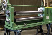
Figure 3Inexpensive slitter heads can be removed by crane, but require careful handling.
OD = coil OD in inches
ID = coil ID in inches
T = maximum strip thickness
t = minimum strip thickness
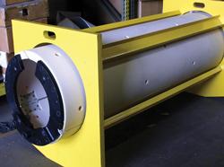
Recoiler drums expand and collapse just enough to allow coil removal, and so they produce just one coil ID size. To produce a variety of ID sizes requires filler plates or interchangeable drums. Changing these plates or drums can cause quite a bit of downtime.
Bolt-on filler plates are available in plastic or steel, but coil processors don't have a choice—steel is required—if no coil car is used to relieve the coil's weight as the coil is pushed off the drum. Some filler plate designs have a fixture to aid in loading, but even with a fixture, installation can be time-consuming. Newer designs have a speed-loading fixture and tabs instead of bolts (see Figure 7) so operators can mount the plates on the recoiler in fewer than five minutes.
Interchangeable recoiler drums also can change the coil ID. This method is more expensive than filler plates, but it eliminates the long tail inherent with filler plate designs. New interchangeable drums feature a quill-type shaft that mounts in a hollow bore reducer. Operators can exchange this type of drum without tools in less than five minutes.
Keeping a close eye on the main areas that affect slitting line efficiency, and using the most suitable equipment in those areas, combined with proper staffing and training, can help coil processors remain competitive in an increasingly competitive industry.


The Fabricator is North America's leading magazine for the metal forming and fabricating industry. The magazine delivers the news, technical articles, and case histories that enable fabricators to do their jobs more efficiently. The Fabricator has served the industry since 1970.
start your free subscription
Easily access valuable industry resources now with full access to the digital edition of The Fabricator.

Easily access valuable industry resources now with full access to the digital edition of The Welder.

Easily access valuable industry resources now with full access to the digital edition of The Tube and Pipe Journal.

Easily access valuable industry resources now with full access to the digital edition of The Fabricator en Español.
In this episode of The Fabricator Podcast, Caleb Chamberlain, co-founder and CEO of OSH Cut, discusses his company’s...


