Graduate Research Assistant, ERC/NSM
- FMA
- The Fabricator
- FABTECH
- Canadian Metalworking
Categories
- Additive Manufacturing
- Aluminum Welding
- Arc Welding
- Assembly and Joining
- Automation and Robotics
- Bending and Forming
- Consumables
- Cutting and Weld Prep
- Electric Vehicles
- En Español
- Finishing
- Hydroforming
- Laser Cutting
- Laser Welding
- Machining
- Manufacturing Software
- Materials Handling
- Metals/Materials
- Oxyfuel Cutting
- Plasma Cutting
- Power Tools
- Punching and Other Holemaking
- Roll Forming
- Safety
- Sawing
- Shearing
- Shop Management
- Testing and Measuring
- Tube and Pipe Fabrication
- Tube and Pipe Production
- Waterjet Cutting
Industry Directory
Webcasts
Podcasts
FAB 40
Advertise
Subscribe
Account Login
Search
Blanking developments - Part I
Fineblanking process and tool design
- By Serhat Kaya and Taylan Altan, Ph.D.
- July 10, 2007
- Article
- Bending and Forming

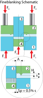
Figure 1: The main purpose of the ejector or counter- punch and V-ring is to generate compressive stresses and hold the material against horizontal movement.
Editor's Note: This is Part I of a three-part series on blanking developments. Part II focuses on part and process design guidelines. Part III covers high-speed blanking and finite element methods.
This column was prepared by Serhat Kaya, of the Center for Precision Forming (CPF, formerly ERC for Net Shape Manufacturing), The Ohio State University, Taylan Altan, professor and director.
Blanking is one of the most frequently used operations in sheet metal forming. Fineblanking, a recent development, produces sheet metal components with smooth edges in a single press stroke.
What Is Fineblanking?
A conventional blanking tool's main elements are a die, guide plate, and punch. The shearing process and a surface's shear quality are influenced by tool geometry and workpiece properties.
Die clearance, cutting-edge radius, and tool wear are the main tool parameters, while blank thickness, mechanical property, chemical composition, microstructure, and sheet material grain size influence material parameters. Die clearance determines the quality and shape of a blanked edge. As die clearance increases, the edges become rougher and the deformation zone becomes larger, which causes the material to pull in and bend.
In fineblanking, in addition to the same tool components needed for blanking, an ejector or counterpunch and a V-ring (4 and 2, respectively, in Figure 1) are used. The main purpose of these tool components is to generate compressive stresses and hold the material against horizontal movement. Three forces—V-ring force (FR), counterforce (FG), and blanking force (FS)—act on the blank. These forces are generated, as shown in Figure 1, by the V-ring (2), the ejector (4), the punch (3), and the die plate (1). FR and FG are applied by hydraulic cylinders.
In general, this operation is carried out on triple-action hydraulic presses on which the punch, guide plate, and die movements are controlled individually. Forces in fineblanking have great influence on a part's quality. During the beginning of the process, FR and FG are applied. These forces provide a firm clamp on the material before blanking begins. FS acts when the press moves down and completes the blanking operation.
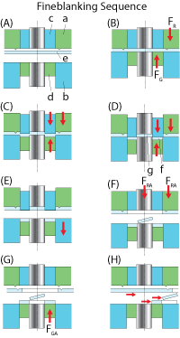
Figure 2 illustrates a complete fineblanking cycle. In (A) the tool is open and the blank is pushed into position. At (B) the main piston is activated, and cutting begins at (C). Once cutting ends (D), hydraulic pressures are released and the tool opens (E). At stages (F), (G), and (H), the strip moves forward. The part and scrap are removed from the tool. Suggested die clearance in fineblanking is 0.5 percent of the blank thickness. In fineblanking presses, the slide always works from the bottom upward. The slide stroke is divided into a rapid closing, touching, blanking, and rapid return travel.
Tool Design
In fineblanking technology, different die types are divided into moving punch and fixed punch systems. A moving punch system is used mainly for blanking dies that produce small to medium-sized parts with few inner forms. The fixed punch system is suitable for all die types, including thick and large parts. The fixed punch system also can be used for progressive blanking dies, compound progressive dies, and transfer dies. Figure 3 and Figure 4 show a schematic view of these systems.2
Fineblanking die design is based on a part's shape, size, type, and the required sheet metal thickness. These parameters determine the type of die and the die system used.
Cut Surface, Die Roll
A fineblanked part's cut surface is sheared smoothly over the entire workpiece thickness (100 percent of s). However, tearing and fracture may occur. While tearing depends on a material's microstructure, fracture behavior is influenced by the magnitude of the blanking clearance.
The die roll depends on blank and material factors such as angle and radius of inward and outward pointing corners, material and microstructure, strength, and sheet metal thickness. In addition to the V-ring, edge preparation of the blanking plate and the punch influence the amount of die roll.
Burr-free fineblanking is not possible. The blanking burr is located opposite the die roll. As a result of tooling wear, burr height and width increase with the number of blanking operations. Burr can be removed by belt or flat grinding.
Notes
- F. Birzer, Forming and Blanking, 2nd ed. (Feintool, 1999).
- Springer-Verlag, Metal Forming Handbook (Schuler GmbH).
About the Authors
Serhat Kaya
1971 Neil Ave. Baker Systems Engineering, Room 339
Columbus, OH 43210
614-292-9267

Taylan Altan, Ph.D.
Professor Emeritus and Director - Center for Precision Forming
Related Companies
subscribe now

The Fabricator is North America's leading magazine for the metal forming and fabricating industry. The magazine delivers the news, technical articles, and case histories that enable fabricators to do their jobs more efficiently. The Fabricator has served the industry since 1970.
start your free subscription- Stay connected from anywhere

Easily access valuable industry resources now with full access to the digital edition of The Fabricator.

Easily access valuable industry resources now with full access to the digital edition of The Welder.

Easily access valuable industry resources now with full access to the digital edition of The Tube and Pipe Journal.
- Podcasting
- Podcast:
- The Fabricator Podcast
- Published:
- 04/16/2024
- Running Time:
- 63:29
In this episode of The Fabricator Podcast, Caleb Chamberlain, co-founder and CEO of OSH Cut, discusses his company’s...
- Industry Events
16th Annual Safety Conference
- April 30 - May 1, 2024
- Elgin,
Pipe and Tube Conference
- May 21 - 22, 2024
- Omaha, NE
World-Class Roll Forming Workshop
- June 5 - 6, 2024
- Louisville, KY
Advanced Laser Application Workshop
- June 25 - 27, 2024
- Novi, MI


