


Contributing Writer
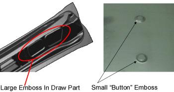 |
| Figure 1 Embossing |
All forming operations deform sheet material by exposing it to tension, compression, or both. Most part defects, such as splits and wrinkles, occur in forming operations. Successful sheet metal forming relies heavily on the metal's mechanical properties. The metal being formed must have the ability to stretch and compress within given limits. It also must be strong enough to satisfy the part's fit and function. This balance between formability and strength often is hard to achieve.
Most forming operations involve at least two basic components: a punch, representing the male portion of the die, and the cavity, representing the female portion.
Although many die types exist, this article focuses on those used in the most common forming operations.
Embossing dies use tension to stretch metal into a shallow depression. The die set primarily is composed of a punch and a cavity. The metal's thickness and mechanical properties, along with the forming punch geometry, determine the depth that can be achieved (see Figure 1).
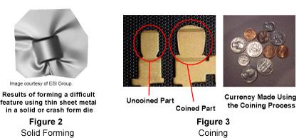 |
Solid form/dead hit dies—also called crash forming dies—deform the metal using only a punch and cavity. These dies do not control metal flow and cannot prevent the metal from wrinkling or buckling. They are used to form simple parts, such as brackets and braces, made from thick, stiff metals that are more wrinkle-resistant than thinner metals. Because this operation also uses tension to form the part, attempting to solid-form difficult part geometries using thin metal often results in severe failure (see Figure 2).
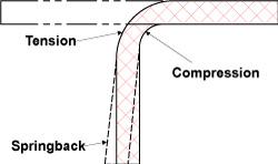 |
| Figure 4 Simple Bending |
Coining dies create the part's shape by squeezing the metal under extreme pressure. Coining also can reduce the metal thickness. Coins (metal currency) are created with the coining process. A simple round metal slug is placed into the die and forced to flow into a given shape by compressing it (see Figure 3).
The restrike die operation fundamentally is a solid forming operation. The main difference is that a restrike die is used after most of the major forming already has been performed. The restrike die's function is to finish forming features that could not be obtained in a previous operation. Restrike dies add details such as sharp radii and small embosses. They also help compensate for springback that occurred during the initial forming.
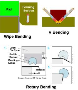 |
| Figure 5 Bending |
A restrike die operation often follows a drawing or trimming operation. These dies, also referred to as qualifying dies, usually use tension to re-form the part; however, compression also can be used.
Bending can be defined simply as a forming operation in which the metal is deformed along a straight axis. Items such as tabs and channels are created using the bending process. Achieving the correct bend angle in a bending operation can be very difficult.
Among the various bending methods are wipe bending, V bending, and rotary bending. All three are very popular, and each has its advantages and disadvantages. Both compression and tension occur during bending. Compression occurs on the inside radius, while tension occurs on the outside radius. Figure 4 shows the compression and tension. Figure 5 shows the three basic bending types.
Flanging is bending metal along a curved axis. Two basic types of flanges are tension, or stretch, flanges, and compression, or shrink, flanges. Tension flanges are susceptible to splitting, and shrink flanges are susceptible to wrinkling.
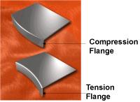 |
| Figure 6 Flanging |
Flanges are created using a flanging die that wipes the metal between a punch and a lower die section. Both tension and compression occur during the flanging process (see Figure 6).
Drawing dies are the most impressive forming dies. Oil pans, automobile doors and fenders, cookware, and door knobs are just a few parts manufactured by drawing.
Draw dies create the part shape by controlling metal flow into a cavity and over the forming punch. Draw dies utilize a special pressure-loaded plate or ring called a draw pad or blank holder to control the metal's flow into the cavity. This plate prevents the metal from wrinkling as it flows into the cavity. Increasing or decreasing the pressure exerted under the pad also controls how much metal feeds into the die. Although compression can occur when the metal is drawn, drawing uses mostly tension to obtain the part geometry (see Figure 7).
 |
| Figure 7 Drawing |
Ironing dies are similar to coining dies in that they deform the metal with compression. However, unlike conventional coining, ironing squeezes metal along a vertical wall. This highly compressive process unifies a wall's thickness and increases the drawn vessel's length. Items such as beverage and soup cans are made using an ironing process. Ironing allows an aluminum can's wall thickness to be reduced to as little as 0.002 in. (see Figure 8).
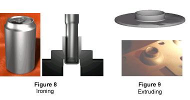 |
In extruding, the metal is flanged around the perimeter of a prepierced hole. Like during stretch flanging, the metal is susceptible to splitting during forming. Extrusions also are referred to as hole expansions or continuous stretch flanges. Often extrusions are tapped for holding fasteners used in the part assembly process (see Figure 9).
Part III of this series will discuss production methods and presses.


The Fabricator is North America's leading magazine for the metal forming and fabricating industry. The magazine delivers the news, technical articles, and case histories that enable fabricators to do their jobs more efficiently. The Fabricator has served the industry since 1970.
start your free subscription
Easily access valuable industry resources now with full access to the digital edition of The Fabricator.

Easily access valuable industry resources now with full access to the digital edition of The Welder.

Easily access valuable industry resources now with full access to the digital edition of The Tube and Pipe Journal.

Easily access valuable industry resources now with full access to the digital edition of The Fabricator en Español.
In this episode of The Fabricator Podcast, Caleb Chamberlain, co-founder and CEO of OSH Cut, discusses his company’s...


