


Contributing Writer
 |
| Figure 1 |
Part VII of this series introduced two basic types of metals used to manufacture stamped parts—ferrous, metals that contain iron, and nonferrous, metals that do not contain iron. This article discusses the specific mechanical properties of these metals in more detail.
The metal's mechanical properties greatly influence the process chosen to transform the flat sheet metal into the finished part's shape and profile. The mechanical properties often influence the tool steel and lubricants used to form and cut the sheet metal. They also determine if offline processes, such as annealing or hardening, are necessary.
Literally thousand of metals are used in stamping today, and it would be nearly impossible to cover each material's specific mechanical properties. This article explains the fundamental properties they all share and discusses methods for testing and defining some of these properties.
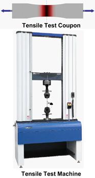
Among the numerous methods used to test metal's mechanical capabilities, the most widely used and accepted is the tensile test. In a tensile test the metal is carefully cut to a specific shape according to a given testing standard. The cut sample is called the test coupon.
The test coupon then is placed into a special machine called a tensile tester, which grabs each end of the coupon and stretches it. The metal is stretched until it fails (breaks). Factors such as how much the metal stretched, how it thinned out, how it changed shape, and how much force was required throughout the entire forming process are carefully measured and documented. Mechanical properties such as elongation percentage, tensile strength, yield strength and nandr valuescan be obtained using this test (Figure 1).
The tensile test also can generate a special graph called a stress/strain diagram (Figure 2). This diagram shows the relationship between the force that is needed and the deformation that occurs. In short, it shows how the metal behaves when being deformed.
 |
| Figure 2 |
Ductility is a very broad term that describes a metal's ability to change shape without fracture. In flat-rolled steel, ductility usually is measured by hardness or mechanical properties in a tensile test. Generally speaking, the more ductile the metal is, the more it can be deformed. However, keep in mind that metal can be deformed in more than one way. Better defining how ductility affects the forming process requires first defining a few important properties that are obtained when the metal is subjected to a tensile test.
Elongation Percentage. Elongation percentage is one of the properties that affect metal ductility. Elongation can be described simply as a numerical expression of how much the metal stretched within a given boundary. The most commonly used boundary is 2 inches.
The metallurgical definition and mathematical equation for elongation can be expressed as the extension of a uniform section of a specimen expressed as a percentage of the original gauge length:
Elongation, % = (Lx- Lo) / Lox 100,
where Lois the original gauge length and Lxis the final gauge length.
For example, a material having 42 percent total elongation stretched 42 percent of its beginning length within a 2-in. boundary before it fractured.
Tensile Strength. Tensile strength can be defined as the maximum stress that a material can withstand. In tensile testing, the measurement is the ratio of maximum load to the original cross-sectional area. Often it is also referred to as the metal's ultimate tensile strength (UTS).
Another definition of tensile strength is the maximum stretching that a material is capable of withstanding without breaking under a gradually and uniformly applied load. Simply, it is the measurement of the breaking or rupturing force.
Yield Strength. A metallurgist may describe yield strength as the point at which material exhibits a determined deviation from the proportionality of stress to strain. While this most certainly is a true statement, it is not one that's easy to understand. Think of yield strength as the measurement of the force necessary to deform the material permanently.
Remember, before a material can permanently change its shape, it must first go through a transition from elastic deformation (not permanent) to plastic deformation (permanent). Think of it like this: Imagine suspending a flat piece of sheet metal that is 0.062 in. thick, 12 in. wide, and 24 in. long between your arms. The sheer weight of the metal will cause it to sag slightly in the center. This change in shape is the result of elastic deformation, meaning that although you have witnessed a change in the metal's shape, the change is not permanent. This can be proven by placing the metal on a flat table, at which point it will return back to a flat sheet.
 |
| Figure 3 |
However, if you severely bow the metal sample and apply enough force, it will begin to take the shape of the bow. The point at which the metal permanently changes its shape is its yield point. Yield strength is a measurement of how much force it took to get the material to deform permanently, give up, or "yield." Yield strength usually is expressed in pounds per square inch (PSI), or megapascals.
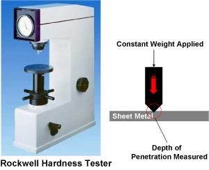
Hardness. Hardness, which can be defined simply as a measurement of the metal's penetrability, usually is tested with a special machine. The most common hardness testing machine is a Rockwell/Brinell tester (Figure 3). This device applies a load or weight to a point that penetrates into the steel's surface. The deeper the penetration, the softer the material. By measuring the applied force and the penetration depth, we can obtain a numerical value that expresses the metal's hardness.
Although hardness alone does not give enough data to determine the metal's formability, it can be used for comparative analyses. Generally, with the exception of metals such as aluminum, the softer the metal, the more ductile it will be. Materials such a copper, brass, gold, titanium, and many other nonferrous metals often are categorized by their hardness.
This article discussed only a few mechanical properties that both ferrous and nonferrous metals have. The next article in this series will cover even more properties.


The Fabricator is North America's leading magazine for the metal forming and fabricating industry. The magazine delivers the news, technical articles, and case histories that enable fabricators to do their jobs more efficiently. The Fabricator has served the industry since 1970.
start your free subscription
Easily access valuable industry resources now with full access to the digital edition of The Fabricator.

Easily access valuable industry resources now with full access to the digital edition of The Welder.

Easily access valuable industry resources now with full access to the digital edition of The Tube and Pipe Journal.

Easily access valuable industry resources now with full access to the digital edition of The Fabricator en Español.
In this episode of The Fabricator Podcast, Caleb Chamberlain, co-founder and CEO of OSH Cut, discusses his company’s...


