


Sales Manager
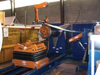
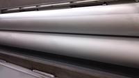
Figure 1: This system includes a coil feed mandrel with full-radius pads, a coil car with a urethane V deck and riser, and a hold-down with a urethane-coated end wheel.
It’s been nearly a century since engineers developed methods to unroll aluminum and steel coil to apply finishing coats or primers, and then recoil the material and ship it out to fabricators and stampers. Today sophisticated press feeding lines process specialty and surface-sensitive materials, such as metals that have been anodized, polished, precoated, or otherwise finished for the end product.
Forming parts from prepainted metals eliminates the high costs of an on-site paint shop and the environmental concerns that go with it. From a cosmetic standpoint, prepainted metal can be formed and shaped with a finish that can be better than surfaces painted or coated after forming and fabrication—surfaces that often carry dirt and residue.Coated coil materials allow appliance manufacturers to introduce new products with specialty finishes that are fingerprint- and bacteria-resistant. In the automotive industry, coil coating provides extended warranty protection against corrosion. In construction, coil coating is the most popular method of finishing metal to look like wood, copper, clay, or other materials.
Processing these materials without degrading the surface requires forethought. Although many of the traditional coil handling rules apply, processing coated coil material requires additional considerations. Be sure to consider the gauge, because the coating itself can change material thickness significantly. You also need to factor in the setup and cleaning of a coil processing line.
In general, carefully evaluate the design of the coil processing equipment (see Figure 1). Materials can be particularly prone to problems during operations such as slitting, recoiling, and cutting to length. You need to check for equipment clearances and alignment at every point where the finished material surface may contact another surface.
Rolls for these applications typically have either a matte chrome coating or a urethane coating that has some give. How the various rolls are balanced and the acceleration and deceleration rates play parts in maintaining the material surface integrity. Gripper feeds can index surface-sensitive materials effectively, but the area where the gripper contacts the coil is often lost as scrap. This is why many use roll feeds for surface-sensitive applications.
In general, the feed design should incorporate the following features:
Full-width matte chrome-coated feed rolls. The major diameter of the feed roll body should be equal to the maximum stock width plus 1 inch. This is a must when running light-gauge material or nonmarking applications. Feed rolls coated with a No. 5 matte chrome finish with a 130-150 RMS (root mean square) can provide necessary traction on the coil strip while still protecting specialty material finishes.
Counterbalance of the upper feed roll. The upper feed roll can be counterbalanced mechanically or pneumatically. Mechanically, air cylinders that lift the upper feed roll can have a built-in spring that counterbalances the weight of the upper roll and pivoting yoke assembly. Pneumatically, an air counterbalance system can offset the weight of the roll and pivoting yoke assembly. Either way allows you to select the optimum amount of force on the coil strip to avoid marking or inducing an edge wave on light-gauge and prepainted materials.
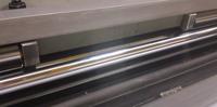
Urethane coating of catenary rollers. Conventional catenary rollers are made with steel rollers. Catenary sections for prepainted and nonmarking applications, however, often have urethane-coated rollers or individual low-inertia rolls (see Figure 2). The soft urethane coating protects the material and allows the catenary section to transition the stock effectively from the slack loop into the servo feed.
Servo roll feeds can handle materials of various widths, thicknesses, and surface finishes, and sophisticated computer controls help monitor and fine-tune feed parameters.
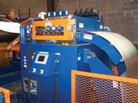
Figure 2: These catenary rollers have a urethane coating for handling surface-sensitive materials. The threading table also has a urethane surface.
Servo feed optimization. Most modern servo feed controls come with a feed adviser or feed optimization feature. This helps fine-tune the feed-move profile based on the feed index length and amount of time allowed to perform the index. The minimum, optimized rates of acceleration and deceleration, as well as the feed velocity, are used to achieve the feed index. This minimizes wear on the servo feed’s mechanical system and reduces the chance of material marking.
S-curve move profile. Servo feed controllers with trapezoid move profiles can have sharp transitions between accel/decel and full velocity of the feed rolls, which can leave witness marks on surface-sensitive materials. A servo feed controller with an S-curve move profile, however, provides smooth transitions between the accel/decel and full velocity, allowing optimum traction without marking the material as the roll feed accelerates to high speeds.
Considerations for the Threading Table
Folding door-type thread tables come in both single- and double-sided construction based on the line width. Pivoting knee-type thread tables also are used in many coil processing lines. Either type can be provided with the necessary features to process surface-sensitive materials (see Figure 3).
Nylon can be bolted to the top surface of the threading table to prevent material marking during initial threading operations. Some tables also have roller surfaces, where rollers along the length of the table support the material to prevent marking when threading the leading edge.
The following considerations are critical for straightener design for nonmarking and surface-sensitive applications.
High-polish chrome rolls. The straightening rolls should be coated with a high-polish chrome finish (see Figure 4). This provides a smooth working finish and is the least likely to pick up debris that can mark surface-sensitive material as it passes through the straightener.
Matte chrome-coated pinch rolls. Straightener pinch rolls should have a No. 5 matte chrome finish with a 130-150 RMS to provide the necessary traction, so they can pull off heavy coils without damaging the material (see Figure 5). In conventional coil lines, the straightener or pinch roll stand must be able to pull off coils weighing up to 50,000 pounds and accelerate the strip up to maximum line speed. In applications with surface-sensitive materials, any slipping between the pinch rolls and coil strip may damage the material.
Air counterbalance of upper pinch rolls. The upper pinch rolls also should have an air counterbalance system to offset the weight of the upper roll. This allows you to select the optimum amount of air pressure and downward force on the coil strip to avoid material marking and edge wave.
Urethane coating of catenary rolls and peeler table. To process prepainted materials effectively, the peeler table and catenary rolls should be urethane-coated. This helps transition the material from the coil reel into the straightener and from the straightener into the slack loop area.
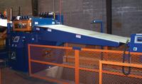
Figure 3: This threading table has a urethane surface for handling sensitive materials.
Coil reels can be configured to work in a pull-off application with power straighteners and roll forming equipment, or they can be provided as payoff reels with the drive mechanism built into the machine to unwind the coil.
Full-radius mandrel pads. Special mandrel pads provide maximum surface contact between the pads and the coil’s inside diameter—sometimes up to 300 degrees of the coil ID (see Figure 1).
Automatic drag brake compensation. This decreases the amount of drag brake tension as the coil size and weight change. An ultrasonic sensor or laser monitors the coil outside diameter and provides a variable, low-voltage signal to a proportional valve system. You set the initial brake pressure, and the automatic system then modulates the pressure to maintain constant tension on the strip as the coil diminishes. This prevents excessive brake pressure and slipping between the coil reel and pinch rolls.
Threading drive assembly with air clutch. Many stampers specify this along with the automatic drag brake compensation to minimize the potential for slippage. The hydraulic threading drive has an integral air clutch to disengage the threading drive during pull-off operations. Engaging the clutch bypasses all back tension from the hydraulic system, and the drag brake sets back tension to further reduce the chance of slipping.
Urethane-coated coil car V deck. This helps transport prepainted coil without damaging the outer wraps (see Figure 1).
Urethane-coated end wheels. In many coil lines, the reel has a hold-down arm with either a powered or nonpowered end wheel. These devices help the threading process and prevent the coil from clock-springing. A urethane-coated end wheel that contacts the coil OD helps prevent surface marking of the coil’s outer wraps (see Figure 1).
Today steel and aluminum sectors combined make up a $100 billion industry. More than 4.5 million tons of coated coil steel and aluminum are processed in North America alone. And the demand for specialty metals is only going to increase.
With proper planning and forethought, you can handle these materials with the right coil feed design. Advanced controls combined with specific threading tables and coated feed rolls work together to handle sensitive material with care, presenting blemish- and scratch-free metal to the forming and fabricating machinery downstream.


The Fabricator is North America's leading magazine for the metal forming and fabricating industry. The magazine delivers the news, technical articles, and case histories that enable fabricators to do their jobs more efficiently. The Fabricator has served the industry since 1970.
start your free subscription
Easily access valuable industry resources now with full access to the digital edition of The Fabricator.

Easily access valuable industry resources now with full access to the digital edition of The Welder.

Easily access valuable industry resources now with full access to the digital edition of The Tube and Pipe Journal.

Easily access valuable industry resources now with full access to the digital edition of The Fabricator en Español.
In this episode of The Fabricator Podcast, Caleb Chamberlain, co-founder and CEO of OSH Cut, discusses his company’s...


