


Contributing Writer
 |
Upon their debut in the 1960s, servo press feed systems were hailed as the technology for the future. They were recognized for their productivity advantages, a result of digital setups that quickly dialed in feed length and speed parameters, with controlled acceleration and deceleration rates, job memory, feedback diagnostics, and velocities that could match most press strokes'.
In the beginning servo drives were expensive and hard to justify, but since the boom in microchips, circuitry, computers, and digital processing, prices have become more comparable to other technologies'.
Even considering the characteristics of servo technology and the price drop in the 1980s, stamping companies still remain reluctant to embrace this "new" technology. Perhaps it's a lack of understanding of how to implement, set up, operate, and train and service the feeds for efficient performance and optimal payback. This confusion results in part from the lack of standardization among press builders and control and feed manufacturers.
Recently there has been a more cooperative effort by all concerned to stop the confusion and allow end users to unify presses, controls, and feeds more easily.
In the days before computers, setting up and programming servo feed systems may have seemed a daunting task. With processors taking over most of the programming calculations, modern press line setups require little more than an operator entering basic run criteria.
Initiation of servo feed cycles is not limited by crank positions, and with a few exceptions, feed can take place from die open to strike. In addition, servos do not require a mechanical reset time and provide a long window of opportunity to complete material feeds, typically resulting in accurate feeds, reduced material waste, and reduced risk of tool damage without a corresponding slowdown in production.
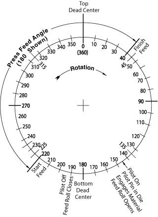 |
| Figure 1 |
For example, feed length is entered via keypad on the feed system's control console or by a wired, remote keypad. With the press of one button, an operator can initiate a single jog feed and verify that the length has been entered and set properly. This test mode, running in slow motion, helps to protect tooling from misfeeds and can save trial-and-error material waste. The length set and jog features also can be used to test sequential feeds in multistation dies.
For press feed angle setup, a fairly simple sensor is attached to the press and networked with the feed controller to provide crank position feedback. The ideal is to allow as much time as possible for material feed, which means the feed angle should be set to start the instant the dies open enough for the material to move and stop just before die strike (see Figure 1). Unfortunately, factors such as ejection of parts and trim stock, strokes per minute, variable press speed control, tool design and clearances, pilot pins, and die protection sensors may disrupt this sequence.
Feed velocity—the speed at which the material is moved into position—can be entered via the keypad and usually is measured in either inches per second, feet per minute, or as a percentage of the feed's maximum rating. The acceleration and deceleration rates—the time it takes for the unit to go from stop to full speed and from full speed to stop—are adjusted by time or as a percentage of the job's velocity. Controlling speed, acceleration, and deceleration lets an operator match the speed of the press and feed cycle to the press, optimizing the operation.
Acceleration and deceleration have become more important recently as changeover and flexibility have become key stamping concerns. The acceleration and deceleration of the feed can be compared to a vehicle that takes off at near full speed from one stop light and arrives with a violent halt to wait at the next light. Nothing is accomplished in getting there faster, except to wear out the engine and brakes faster and use more energy.
The same can be said for press feeds. If the material arrives and the die is not ready to stamp, no productivity has been gained, but wear on the feed mechanism and die components, the chance of stock buckling, and the chance of slippage that can cause long or short feeds are greatly increased. Gradual acceleration and deceleration can help optimize the process.
Die protection systems, which are becoming more popular, rely on sensors to monitor material presence and help ensure part ejection in the tooling to eliminate the potential for partial and double-up hits. Because the sensing for the presence or absence of material has to wait until the feed cycle is done so the die protection system has ample time to do its job and stop the press, the feed cycle has to be completed sooner. In some cases, a die protection system may reduce the time available for feeding stock by 20 percent or more.
A second element to consider is variable speed throughout the stroke of the press, such as with link-motion and servo-driven presses. Variable speed allows the operator to set different speeds within a single stroke cycle, like a rapid traverse to a machine tool.
For example, from about 190 degrees to 120 degrees, the stroke speed can be set higher, then slowed to stamp. This results in a much shorter available feed time, and thus requires either a slowdown of the press or faster feed velocity with corresponding greater acceleration and deceleration rates. Fortunately, servo controls allow easy change of these measures, along with a level of precision control that helps fine-tune press and feed synchronization.
Once length, angle, velocity, acceleration, and deceleration rates have been set through the control, three parameters remain that, though not under the watch of the controller, have to be set for optimal press efficiency and quality: feed roll pressure, pilot pin release timing, and passline height.
Compensation is the next step in press line control. Two-way communication between the feed and press automatically compensates for variables or set parameters. This type of control can prevent changes in the setup at one piece of equipment without a corresponding change or alarm at another.
For example, if the press speeds up, compensation must be made at the press controller and the feed control for the faster rate, in terms of when to generate signals, the required stop time for the die protection system, and pilot release timing.
Compensation also allows the operator to decide how to enter program information: either with a single interface such as the press control or with the features of both controls. Modern controllers also allow toggling between inch-/foot-based measurements and metric units, memory storage for nearly limitless job runs, and recall by part number. Feed length, speed, acceleration/deceleration rates, and feed angle can be stored, recalled, and set automatically.
More highly automated setup procedures incorporate a programmable logic control interface and smart valves. Information is sent to the feed rolls to set pressure and to auxiliary equipment such as straighteners to adjust straightening rolls automatically for specific job needs. The ultimate level of control comes when PC-based controllers monitor the entire process, watching the press with programmable limit switches that automatically modify feed parameters in real time to match the press cycles continuously.
Some control systems now include feed angle monitoring, which observes the percentage of the stroke being used for feed. If the control determines the feed is taking too high or low a proportion of the stroke, the velocity may be increased or decreased to a level that optimizes the press and feed cycles for maximum productivity and part quality assurance.
Because of the productivity potential of presses and automated feed lines, setup procedures have become the most critical part of pressroom operation. Subsequently, the key element to hitting the mark with correct setup is training. Operators and die set personnel must be fully aware of and comfortable with using all the features that today's servo control feed systems offer.
Feed automation suppliers should spend whatever time is necessary to work with supervisors, operators, setup technicians, and maintenance personnel to demonstrate all the features of their servo-controlled feeds. Although the task of coordinating press and feed lines can be complex, the job of setting up and operating press and feed lines can be simple thanks to today's advanced feed control technologies.
Brian Landry is regional sales manager with Dallas Industries Inc., 103 Park St., Troy, MI 48083-2770, 248-583-9400, fax 248-583-9402, www.dallasindustries.com.


The Fabricator is North America's leading magazine for the metal forming and fabricating industry. The magazine delivers the news, technical articles, and case histories that enable fabricators to do their jobs more efficiently. The Fabricator has served the industry since 1970.
start your free subscription
Easily access valuable industry resources now with full access to the digital edition of The Fabricator.

Easily access valuable industry resources now with full access to the digital edition of The Welder.

Easily access valuable industry resources now with full access to the digital edition of The Tube and Pipe Journal.

Easily access valuable industry resources now with full access to the digital edition of The Fabricator en Español.
In this episode of The Fabricator Podcast, Caleb Chamberlain, co-founder and CEO of OSH Cut, discusses his company’s...


