


Contributing Writer
This article is Part II of a two-part article on die design for bending.
There are several good ways to design a tool to achieve a 90-degree bend. Whatever method you choose, you must be able to adjust the tool easily in response to variables discussed in Part I of this series.
To achieve a 90-degree bend, you must overbend the material past the desired bend angle and allow it to return to the desired shape with the springback.
 |
| Figure 1 |
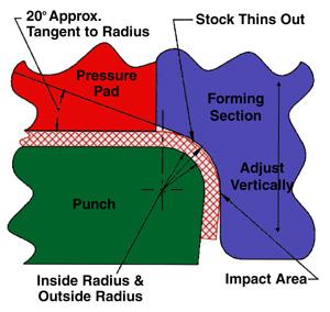
Figure 1 shows perhaps one of the simplest die designs that can achieve a 90-degree bend. However, keep in mind that this design works best for bends that have an inside bend radius that is equal to or less than 1x metal thickness. This design allows the metal to be coined or impacted on the one area of the bend that is most advantageous. In addition, it can be adjusted easily to decrease or increase the severity of impact by shimming or grinding the forming section.
This design is based on the premise that metal-when bent around a small inside bend radius-will thin as much as 25 percent at the midpoint between the tangents of the radius. The following are the initial guidelines:
The advantages to this style are:
Disadvantages include:
 |
| Figure 2 |
Figure 2 shows what is commonly known as a rocker, or ready bender. It is a patented method for achieving straight-line bends, produced by a company called Ready Technology, Inc. This method uses a single bending unit comprising two primary components, the saddle and the rocker. This unit can be mounted on upper or lower die shoes.
During bending the rocker acts as both a holding pad and forming steel. As the press continues downward, the rocker rotates, creating a gentle bending action. Because of this rotary action, a primary bend angle of about 120 degrees can be achieved. If you are bending prepainted material, an additional pad and a rocker inserted with Delrin® can be included with the unit to prevent marking the panel.
Advantages of this design include the following:
Disadvantages of this method include:
 |
| Figure 3 |
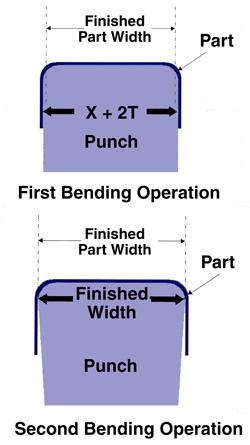
Figure 3 illustrates a good way to achieve a 90-degree bend in a two-station operation. This type of design works best with progressive and transfer dies made for U-shaped parts. Although this design works for one-sided bends, the holding force exerted by the pad must be increased to keep the part from skidding during bending.
The material first is prebent over a post that is slightly wider than the finished part. This difference in post width is a function of the inside bend radii size and the desired amount of overbend. A good rule of thumb is to make the first bending operation 1x metal thickness per side larger than the finished width. This prebend can be a partial or complete wipe bend, depending on the amount of overbend that is desired.
A conventional wipe-bending operation follows this prebending operation. The objective here is to create a prebent area in the part that eventually ends up near or in the vertical wall of the second and final bending operation. Adjusting the amount of overbend in the first operation increases or decreases the amount of overbend in the second and final operation.
Advantages of this type of operation are:
Disadvantages are:
 |
| Figure 4 |
Figure 4 shows a good way to achieve a 90-degree bend in a progressive die. There is nothing extraordinary about this design, other than that the part has been rotated from its normal axis to allow it to be V-formed, as opposed to wipe-formed.
After the V-forming has occurred, the part is restruck back to a flat shape. If flatness is a critical part feature, you should try to bend the material in the area of the part carrier that will become scrap, because it is difficult to bring the bent area back to a perfectly flat state.
Advantages of this method are:
Disadvantages are:
 |
| Figure 5 |
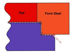
I often am asked if a double bend can be created in a single operation. The answer is yes. However, once key design characteristic must be incorporated in a double-bending operation-decreased contact area of the lower forming section.
Figure 5 illustrates a typical double-bend operation. This design creates a double bend, but the finished parts have a tendency to curl slightly on the vertical wall between the bends. This curling is the result of intense bending and unbending over the forming punch radius. The severe bending action creates tension on one side of the material and compression on the opposite side, resulting in a curling effect much like cookie dough on a rolling pin.
 |
| Figure 6 |
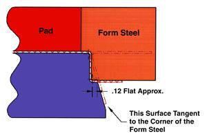
To reduce curling, you must reduce the severity of the bending action by reducing the contact area of the lower forming section (see Figure 6). A good rule to remember is to limit the amount of flat on the lower forming section to 2x metal thickness past the tangent of the outside bend radius.
Remember: Whatever bending method you choose, make sure it can accommodate adjustments easily, and your operation will be the better for it.


The Fabricator is North America's leading magazine for the metal forming and fabricating industry. The magazine delivers the news, technical articles, and case histories that enable fabricators to do their jobs more efficiently. The Fabricator has served the industry since 1970.
start your free subscription
Easily access valuable industry resources now with full access to the digital edition of The Fabricator.

Easily access valuable industry resources now with full access to the digital edition of The Welder.

Easily access valuable industry resources now with full access to the digital edition of The Tube and Pipe Journal.

Easily access valuable industry resources now with full access to the digital edition of The Fabricator en Español.
In this episode of The Fabricator Podcast, Caleb Chamberlain, co-founder and CEO of OSH Cut, discusses his company’s...


