


Contributing Writer
In this global and competitive economy, especially now, it is imperative that production sheet metal stampers get the maximum part count by consuming the least possible amount of material.
Most production stampers that use plain carbon steel sheet get about 5 percent of their original material cost back when selling scrap to a scrap dealer. Sometimes the costs of handling this scrap even outweigh the return gained from selling it. Saving even a fraction of a cent per piece part may be the difference separating you from your competition. Large automotive companies have invested great amounts of money and have assembled teams whose sole function is to utilize and reduce scrap in their stamping operations.
 |
| Figure 1 |
Aside from the usual rotation of a blank configuration and common nesting practices, there are other ways to reduce scrap in progressive dies. First of all, consider nesting more than one part type in a single strip layout.
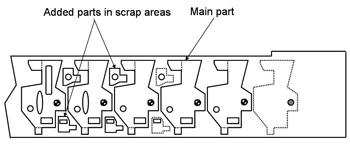
As a consultant, I often see parts made from the same material type and with the same thickness stamped in two separate progressive dies. On occasion I notice that one of the parts could have been nested into the scrap areas of the other die. In other words, both parts could have been stamped with the same die.
One common problem with nesting two different parts in a common die is that their needed production volumes may differ. A good rule of thumb to help solve this is to make sure that the production volume for the larger of the two parts is greater. This way, the amount of material needed to produce the larger part won't be wasted while only the small part is running.
If the smaller parts are not needed, simply discard them as scrap. With the exception of some slight unnecessary die wear, you most likely will be no worse off than if you hadn't designed the smaller part in the tool.
Utilizing a single progressive die to produce two (or more) parts not only reduces total tooling cost, it eliminates the need for another press and operator. This savings can be enormous.
 |
| Figure 2 |
Keep in mind that because of other variables, such as product design and the needed strokes per minute, nesting two parts may not be to your advantage. For example, nesting a small, low-production, deep-drawn cup in the scrap areas of a larger, simple pierced and bent part may slow down production speed dramatically because the speed at which metal can be drawn typically is much lower that the speed at which it can be bent and pierced. In this case, nesting the drawn cup to the scrap area will reduce the speed at which the larger, high-production part can be produced.
Figure 1shows a strip layout for producing three different parts in a common progressive die.
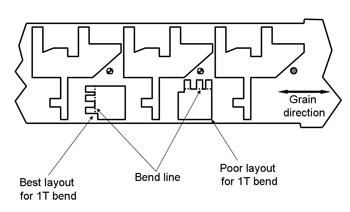
It also is important to pay attention to the sheet material's grain direction when nesting two parts, especially when forming or bending high-carbon, high-strength sheet steel. In other words, even though a product can be nested easily into the scrap areas of an existing die or layout, it is important to analyze the bending direction with respect to the steel's grain direction. Bending parallel to or with the steel grain over a small inside bend radius may result in cracking on the outside of the bend. Bending against the material's grain may yield better results (see Figure 2).
The use of offal, or recovery, dies is not uncommon in stamping shops worldwide. A lot of shops use their scrap to produce other parts. For most offal die operations, the scrap is hand-loaded into a line die or sometimes into a transfer system.
Here's a different spin on utilizing this scrap: Consider using it to produce a continuous strip that can be fed into a progressive die.
 |
| Figure 3 |
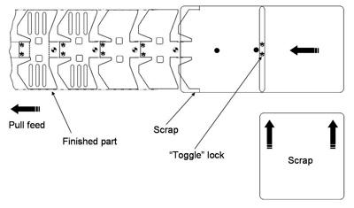
A progressive die is one of the fastest ways to produce a stamped part. Scrap areas of larger parts can be stitched or fastened together using a variety of commercially available metal locking devices, such as Toggle LockTM. With a little mechanical creativity, offal can be loaded into the progressive die and stitched together to create a continuous strip. The strip can be pulled through the die rather than conventionally pushed through with a push-pull machine. Even multiple parts can be nested in the scrap's scrap area (see Figure 3).
It is important to remember that once metal has been deformed in the first operation, the resulting scrap most likely will have lost a certain amount of ductility and may not have the same forming characteristics. This is extremely important to consider when using certain types of steel, such as bake-hardenable or high-strength. For example, using the scrap from an automotive window opening made of bake-hardenable material to form a shallow bracket or support may work fine. However, using this pre-strained, work-hardened material to form a deep-drawn part may result in failure.
Using scrap effectively requires everyone's cooperation, including product designers, production engineers, and tooling personnel. Slight product design changes may allow the part to be nested in the scrap areas of a pre-existing tool.
In addition, choose your offal wisely, and avoid using severely work-hardened material for deep-drawn products.
Although the concepts discussed here may not be always be achievable, it is important to consider the available options. For example, for automotive parts that require less strength for crash absorbency, designers might consider using slightly thicker materials and cutting out areas on parts that need to collapse on impact. Even though the part might weigh more (depending on how much metal was removed to weaken it), the production cost savings may well outweigh the cost of increasing the metal thickness.


The Fabricator is North America's leading magazine for the metal forming and fabricating industry. The magazine delivers the news, technical articles, and case histories that enable fabricators to do their jobs more efficiently. The Fabricator has served the industry since 1970.
start your free subscription
Easily access valuable industry resources now with full access to the digital edition of The Fabricator.

Easily access valuable industry resources now with full access to the digital edition of The Welder.

Easily access valuable industry resources now with full access to the digital edition of The Tube and Pipe Journal.

Easily access valuable industry resources now with full access to the digital edition of The Fabricator en Español.
In this episode of The Fabricator Podcast, Caleb Chamberlain, co-founder and CEO of OSH Cut, discusses his company’s...


