


Press Automation Manager
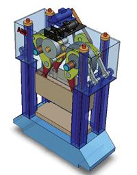
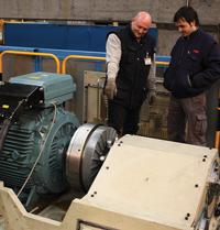
This servomotor upgrade kit was installed on top of a mechanical press. The press slide uses energy from both the servomotor and the flywheel.
The mechanical press is this industry's workhorse for a reason. It has worked well for decades. The flywheel stores potential energy and, through eccentric drives and gears, transforms it into kinetic energy to produce the tonnage required to form metal. It's here, during metal forming, that the flywheel shows its mettle.
But at other points in the stroke—not so much.
After reaching bottom dead center (BDC), the slide rises relatively slowly to top dead center (TDC). During that time, when the ram isn't touching the workpiece, the press's motion is not adding value.
What matters from a press productivity standpoint is the press line cycle. In a line with robotic loaders, the cycle consists of two parts: one determined by the press, the other by the robots. The robot cycle time involves the loading and unloading of the press. Typically, unloading starts as soon as the press has opened sufficiently for the unloader to enter it, and the ram moves downward before loading is fully complete. Optimizing robot placement, synchronizing different robots on the line, and using specialized seventh-axis motion have reduced the robot's cycle time from more than six seconds five years ago to less than three seconds today, even for large parts (see Figures 1 and 2).
The robots' shorter cycle time, though, has made the press cycle time a more important factor in the overall line cycle time. Several challenges arise when trying to increase press speed and flexibility. The press's flywheel can handle only so many strokes per minute (SPM). Exceeding a certain SPM rate risks damaging the flywheel. Also, the part often can be formed only so fast, and going beyond a certain SPM may cause quality issues.
However, a new servo-drive technology—retrofitted onto an existing mechanical press—may overcome these challenges.
Introduced by robotics-maker ABB, Dynamic Drive Chain technology, or DDC®, involves a servo-drive upgrade kit retrofitted into an existing or new mechanical press (see Figures 3 and 4). It permits the press to open and close faster while maintaining the original speed for pressing, when the machine actually forms metal.
The DDC upgrade kit turns a traditional mechanical press into a hybrid machine that uses power from two sources: the press's existing flywheel and a new servomotor drive integrated into the press. During metal forming, the ram draws power from the flywheel. After BDC, the servomotor accelerates the slide to TDC, then back down. Before impact, the servo-drive gears synchronize with the speed of the main shaft and flywheel, and the flywheel clutch is engaged for the next forming cycle.
It's a bit like a hybrid car. The car optimizes performance by using the electric motor and/or gasoline motor according to the load-condition requirements. In the mechanical press upgraded with a servo-drive kit, the flywheel does its work to form the metal. At all other times, the servomotor powers the slide.
Although the flywheel does have a maximum SPM, the press's internal gears actually can be driven faster. So when the upper die isn't touching the workpiece, the servomotor can actually drive the slide faster than would be possible with the flywheel.
Figure 1Advances have reduced robotic cycle time from six seconds five years ago to three seconds today, even for large parts
The servomotor also slows and stops the slide. The mechanical press's existing brake engages only for the rare emergency stop. Because the brake is rarely if ever used, its life is extended greatly. Partly because of this, the upgrade requires a press to have a separate clutch and brake. If a press has an integrated clutch and brake, it can be replaced with a separate clutch-and-brake setup as part of the upgrade.
To perform the upgrade, engineers install a servo-drive kit—including an AC servomotor and associated gears to interface with the press drive train—which works with the press's existing flywheel, AC motor, and clutch. If the flywheel motor is DC, it has to be replaced with a new AC flywheel motor as part of the retrofit. Both the new servomotor and the flywheel motor are controlled by a new multidrive and a new controller—the "brains" of the system.
In addition, a servo upgrade can reduce stress on the overall system. In a conventional mechanical press, at TDC, when the press is stopped and waiting for the automation to do its job, the clutch engages as the flywheel rotates at full speed—a bit like popping the clutch on your car while the engine is at high RPM. In a system upgraded with a servo, the control tells the servomotor to bring the press drive train to a synchronous speed with the flywheel. So, as the flywheel clutch engages, both the drive train and the flywheel have the same speed. It's a bit like an experienced driver shifting gears in a car; it's a smooth, almost seamless transition, and much easier on the clutch. This fact minimizes the clutch wear, which is one of the main maintenance issues in a mechanical press.
Note that the original flywheel configuration isn't altered, so if needed, the servomotor can be disconnected and the mechanical press can operate as it did before the upgrade. In other words, the upgrade is backward-compatible.
The system requires low peak power, which usually does not require redimensioning the factory's power grid. Several factors make this possible.
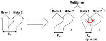
First, the press uses what's called multidrive technology. One drive controls both the existing flywheel motor and the newly installed servomotor, allowing energy to be interchanged between the two. During the forming portion of the cycle the multidrive allows the servomotor also to send power to the flywheel. This load sharing means that both the servomotor and the flywheel motor can run at lower peak power (see Figure 5).
For instance, in a recent installation in a 1,600-ton press, the flywheel motor has 160-kW peak power, and a servomotor has 306-kW peak power. Theoretically, both of them should have 466 kW of peak power—but they don't. Because they share the load through the multidrive, the system draws only 210 kW of peak power from the factory grid.
Less energy is wasted in the clutch operation, too, because the clutch engages only when the servomotor's gears rotate synchronously with the flywheel's gears. Also, energy isn't wasted from the brake, which operates only for emergency stops.
This technology makes business sense when trying to increase capacity or when you need to improve quality without affecting throughput.
Consider some hypothetical numbers. Say a series of presses has internal gears that can run the slide up to 25 SPM, but it doesn't because running this quickly would damage the flywheel. Also, at the initial forming station, the workpiece can handle only 14 SPM; if it runs faster than this, part quality may suffer. That's a bottleneck affecting the production of the whole line. When the upper die touches metal, the ram must not move faster than 14 SPM. But this isn't true at all other points in the stroke—and this is where a servomotor upgrade can help.
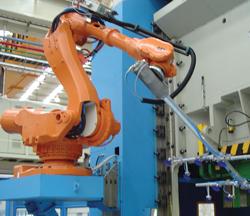
Figure 2While robot cycle time has reduced, a bottleneck remains within the cycle of a mechanical press, especially at the initial forming station.
With the upgrade, a press's servomotor accelerates the ram motion after BDC to 25 SPM, bringing the slide to TDC at full speed, then back down, slowing it to a synchronous speed with the flywheel, just before the upper die contacts the workpiece. At this point, the clutch engages to drive the upper die into the metal at 14 SPM. This increases throughput and maintains part quality at the same time. Applications such as this have the potential to increase the net output by up to 30 percent, depending on the existing conditions.
Since the global downturn began, increasing capacity hasn't been top of mind for many. But quality concerns never go away. Say a part running at 14 SPM has quality problems. These may be solved by slowing the press to 10 SPM. To maintain throughput, the servomotor accelerates the slide through the rest of the stroke, then decelerates to 10 SPM, the flywheel's speed, just before hitting the workpiece. At this point, the flywheel clutch engages and the metal is formed. The result: The press forms the part at a slower rate, improving part quality, but overall throughput is maintained or even increased.
Such an upgrade kit can be installed without a robotic load/unload setup. But if used with certain robots, the upgrade allows motion of the press slide and robots to be fully optimized. When the servomotor changes the speed of the press stroke, the robots change their motion to accommodate.
The result is continuous press operation, with coordinated motion of the cycle time in both the press and robotic components of a stamping line. This allows the mechanical press—the industry's workhorse—to become more productive, flexible, energy-efficient, and, in many cases, take full advantage of advances in automation working within and around the work envelope of the mechanical stamping press.


The Fabricator is North America's leading magazine for the metal forming and fabricating industry. The magazine delivers the news, technical articles, and case histories that enable fabricators to do their jobs more efficiently. The Fabricator has served the industry since 1970.
start your free subscription
Easily access valuable industry resources now with full access to the digital edition of The Fabricator.

Easily access valuable industry resources now with full access to the digital edition of The Welder.

Easily access valuable industry resources now with full access to the digital edition of The Tube and Pipe Journal.

Easily access valuable industry resources now with full access to the digital edition of The Fabricator en Español.
In this episode of The Fabricator Podcast, Caleb Chamberlain, co-founder and CEO of OSH Cut, discusses his company’s...


