


Contributing Writer
 |
Because metal fabricators and OEMs have increasingly strict requirements, many suppliers of sheets and blanks must provide high-quality metal stock in terms of flatness, finish, and dimensional accuracy. Competition for every bid is tight, making it easy to take the quality for granted. If every supplier offers the same quality, quality becomes a commodity, and a supplier can't use it as a differentiator to generate revenue. Profit margins shrink, and suppliers must find different ways to survive.
Getting orders and making money now depend greatly on line productivity. If you can't make it better, you'd better make it quicker.
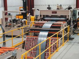
One of the first decisions to make when setting up a cut-to-length line is whether it will run in tight-line mode, free-loop mode, or both. Tight-line machines run in a stop/start fashion if equipped with a stationary shear or in continuous mode if equipped with a flying shear. In either case, a leveler or straightener measures and feeds material to the shear.
Tight-line System. Tight-line configurations can be a good choice if floor space is limited, because they usually are shorter than free-loop designs. They have lower foundation costs because a looping pit isn't required, and the thickness capacity of tight-line machines is virtually unlimited, making them ideal for heavy-gauge applications.
Tight-line machines with stationary shears have the lowest cost of any cut-to-length line, but have the lowest productivity as well. In addition, tight-line machines may damage thinner materials because visible roll marks can appear where material stops in the leveler. The design is, however, well-suited for material that is too thick to run in a free loop.
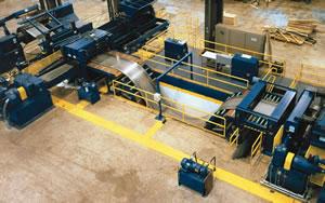 |
| Figure 1 A free-loop accumulator has a pit into which the strip is fed; as the name implies, a tight-line system does not require a pit. |
A tight-line machine with a flying shear has better productivity than one with a stationary shear, but length accuracy is more difficult to achieve. This is because the flying shear, a machine with substantial mass, must be synchronized perfectly with the speed and location of the moving strip. Synchronization can be achieved, but the cost is usually substantial, and the length tolerances usually are rather loose. This design is well-suited for lines equipped with a skin pass mill, sometimes installed to improve flatness and surface quality, because this type of mill has far too much mass to start and stop efficiently.
Free-loop System. Another operating mode in cut-to-length lines is the free loop (see Figure 1). In a free-loop setup, a leveler or straightener feeds material at a constant rate into a loop. At the other end of the loop, a separate feeding device measures and feeds the material to the shear. For the leveler to run at a constant rate, the feeder runs faster than the leveler, stops while the shear makes the cut, then runs faster again. Loop depth increases while the feeder is stopped, and decreases while the feeder is moving. To maintain flatness after leveling, catenary guides with very large radii guide the material into and out of the loop. With proper guides, material up to 0.250 inch thick can be handled efficiently in free-loop systems.
Because they offer good quality and productivity at a reasonable cost, free-loop systems are commonly used, particularly in light-gauge applications. Two feeder designs commonly used in these lines are hydraulic hitch feeds combined with a hydraulic shear and servo roll feeds combined with a mechanical shear. These designs are similar in some ways, and different in others.
Hitch feed systems have been in use since the 1950s. They generally provide good accuracy and quality. Hundreds, if not thousands, of these machines have been put into service over the years. They typically have low initial cost, but the feed/stop/reverse cycle limits their productivity.
To cycle a hitch feed system, two movable clamps are applied to the edges of the strip. Once applied, a hydraulic motor pulls a chain connected to the clamps and propels them forward. This motion continues until the clamps hit a positive stop, which is mechanically set to the required sheet length. After the motion stops, two stationary clamps are applied to the strip. The hydraulic shear then makes the cut, and the blade returns to its initial position. The movable clamps then are released, propelled backward to their original starting position, and the cycle is ready to start again (see Figure 2).
If the sheet length desired is longer than the hitch feed track, the clamps move forward to feed half the length, move backward, and then move forward again to finish the feed. Some hitch feed systems have the ability to clamp one side of the strip and then the other in an alternating fashion. This increases line productivity by taking the reversing time out of the cycle, but it decreases the ability to hold accurate length and squareness tolerances.
 |
| Figure 2, Figure 3 Figure 2: A hitch feed cycle includes both forward motion (the movement plotted above the X axis) and reverse motion (the movement plotted below the X axis). The cycle time includes the time needed to move forward, stop, move backward, and stop again. Figure 3:A servo roll feed moves forward only, so its cycle time is shorter than a hitch feed's cycle time. |
In recent years several advances have been made to improve the speed of hydraulic shears. With the use of special pumps and cylinders, some hitch feed systems can attain production rates of 45 pieces per minute on short lengths.
Servo roll feed systems became commonplace in the 1970s when accurate, reliable servomotors became widely available. These systems provide good accuracy and quality, and although they have a higher initial cost, their feed/stop cycle facilitates high productivity (see Figure 3).
To cycle a servo roll feed system, a pair of specially designed feed rolls are applied to the strip. The rolls are hollow to reduce inertia and conform easily to any crown present in the strip. A servomotor connected to the rolls drives material through the shear and stops. The shear makes the cut, and the blade returns to its initial position.
In multiblanking applications, servo roll feeds are equipped with full-width rolls. Unlike hitch feeds that grip the outside edge of the strip, full-width rolls can feed multiple strips into the stacker. This is important because it allows the slitter in a servo roll feed multiblanking line to be placed before the looping pit, the same place it is located in every slitting line. Locating the slitter before the looping pit allows it to run at a constant speed instead of starting and stopping under quick acceleration and deceleration conditions with the feeder. Knife life is greatly improved, scuffing is eliminated, and material can be fanned out, allowing easier multiblank stacking.
At the heart of a servo roll feed system is the motion controller, which performs advanced and real-time calculations to move and measure the strip. After an operator programs the length, material type, and batch size, the motion controller calculates optimal acceleration rate, tracks piece length and batch size, and provides master motion control for the entire cut-to-length line.
The ability to control the entire line is an interesting side benefit of servo roll feed systems. The motion controller in these lines can coordinate tight-line as well as free-loop operations. This means a single line can efficiently run light-gauge material in loop mode and heavy-gauge material in tight-line mode.
Rather than using mechanical end stops, servo roll feed systems control piece length by counting the pulses generated by an encoder mounted on the servomotor. Resolutions of 0.0001 in. per pulse are possible with the use of state-of-the-art encoders, making piece length tolerances of ±0.005 in. attainable in real-world conditions.
When the motion controller is finished moving the strip, a mechanical shear typically makes a single cut to complete the cycle. This is known as free-loop roll feed mode with a stop/start shear. Many roll feed lines use this system with an AC-motor-driven mechanical shear, which allows production rates up to 60 pieces per minute on short pieces.
When equipped with a variable-speed motor, however, the shear can run continuously if desired. In this mode, material is fed while the knife is still moving, and the material stops before the knife enters the material again. This is free-loop roll feed mode with a continuous shear. This mode allows production rates up to 100 pieces per minute on short pieces.
In electrical jargon, the act of accelerating, moving, and decelerating strip for a precise distance in a finite amount of time is called a move profile. Although the move profile is calculated by the motion controller, some systems allow operators to fine-tune the profile to accommodate different material thicknesses and surface conditions. Running a cut-to-length line is, in some ways, similar to driving a car. In a car, your speed depends greatly on road conditions and the speed limit. In a cut-to-length line, your speed depends greatly on material conditions and tolerance limits. Your goal is to run as fast as you can while still meeting or exceeding customer requirements.
It's interesting to note that most slippage occurs during a change in the rate of acceleration, sometimes called jerk, and not during a constant acceleration rate. For example, if the desired acceleration rate is 800 feet per minute (FPM) per second, slippage is more likely to occur during the transition from 0 FPM per second to 800 FPM per second than it is once a constant acceleration rate of 800 FPM per second has been reached. Knowing this, you can program gradual transitions to eliminate slippage and achieve good move profiles.
Two fields of thought offer opposing views on surface-critical material. One camp thinks that hitch feed systems are superior for running surface-critical material; the other camp states that hitch feed and servo roll systems run surface-critical material equally well.
The rationale of the former perspective is that the high clamping forces over the small contact area on servo roll feed systems can mar the surface of the metal. This line of thinking assumes that these systems need the same clamping force even though they operate under radically different acceleration conditions. A hitch feed system spends half of its time in reverse, whereas a servo roll system does not. These two acceleration conditions require different clamping forces.
According to the latter perspective, servo roll feed systems achieve excellent productivity at relatively low acceleration rates because they drive only forward. Low acceleration rates eliminate slipping and require less clamping force. With zero slipping and low clamping force, the possibility of strip damage is low. Servo roll feed systems are, in fact, currently used all over the world to process many kinds of surface-critical materials, including exposed automotive panels, prepainted appliance skins, and polished stainless steel.
Many sheet and blank suppliers have seen quality demands increase, but most customers are unwilling to pay extra for better quality. While many cut-to-length lines can deliver a high-quality product, they vary greatly in terms of productivity. An ideal machine in this market doesn't just produce parts with excellent flatness, finish, and accuracy; it produces them quickly.
Kenneth F. Shoop is southeast regional manager of Braner USA Inc., 9301 W. Bernice St., Schiller Park, IL 60176, 847-671-6210, fax 847-671-0537, braner@braner.com, www.braner.com.

The Fabricator is North America's leading magazine for the metal forming and fabricating industry. The magazine delivers the news, technical articles, and case histories that enable fabricators to do their jobs more efficiently. The Fabricator has served the industry since 1970.
start your free subscription
Easily access valuable industry resources now with full access to the digital edition of The Fabricator.

Easily access valuable industry resources now with full access to the digital edition of The Welder.

Easily access valuable industry resources now with full access to the digital edition of The Tube and Pipe Journal.

Easily access valuable industry resources now with full access to the digital edition of The Fabricator en Español.
In this episode of The Fabricator Podcast, Caleb Chamberlain, co-founder and CEO of OSH Cut, discusses his company’s...


