


Eddy current testing strategies for copper tube
How and where to test
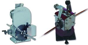
Stationary sensors (through-coil type, left) and scanning sensors (rotating type, above) differ in modes of operation and flaws they detect. Through-coil sensors are well-suited for finding small, deep flaws; rotating sensors are designed to find long, shallow flaws.
Nonferrous tubes are manufactured for a variety of applications and consequently must meet appropriate standards or requirements. Some of these requirements relate to testing for leaks and others relate to verifying the quality. Eddy current testing, a nondestructive testing technique, is suitable for such applications.
Testing copper tubes is particularly important because most of them are used for air-conditioning and refrigeration (ACR) applications, heat exchangers, and so on. For example, a hole in an ACR tube creates several problems—loss of the refrigerant, loss of system efficiency, and a troubleshooting headache.
Manufacturing standards stipulate minimum requirements, many of which can be met using an eddy current apparatus with a through-type coil. However, some manufacturers must go beyond published standards. As raw material costs rise, manufacturers decrease wall thicknesses to reduce costs, so they must apply increasingly stringent testing requirements. They often use rotating scanning probes, which provide higher flaw resolution than through-type coils.
Testing Seamless or Welded?
The most common copper tube manufacturing methods are extrusion, cross-rolling from rod stock, and continuous hollow casting. The tubes are further processed by cold pilger rolling, planetary rolling, and drawing. The step for achieving the final size usually involves a drawing process. The end product is supplied either cut to length or coiled.
On the other hand, welded copper tube output is on the rise because tube producers can form various surface structures in the flat strip before forming it into a tube.
Whether the tube is seamless or welded, two commonly used test methods are through-coil and rotating scanning probe. These two methods differ in how they work and the flaws they detect.
Through-coil. A through-coil setup is a stationary induction coil through which the tube moves (see Figure 1). This is the most frequently used eddy current test method. It is suitable for product diameters from 0.3 mm to 240 mm (0.12 inch to 9.47 in).
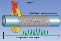
Rotating Scanning Probe. A rotating scanning probe is a device with either two or four probes mounted to a rotating scanning head; the tube passes through the ring. The scanning probes track a helical pattern around the tubing (see Figure 2). These units are sensitive to long, shallow flaws.
Driven by motors that run up to 18,000 revolutions per minute, rotating probes are suitable for detecting flaws as shallow as 30 µm on tube traveling at tube mill speeds. Typical scanning capabilities are:
- For 2 mm — 20 mm (0.079 in. to 0.787 in.) diameters, a scanner with two test heads at 18,000 RPM can test up to 3 m per second (590 feet per minute).
- For 2 mm — 35 mm (0.079 in. to 1.378 in.) diameters, a scanner with four test heads at 9,000 RPM can test up to 3 m per second (590 FPM).
- For 5 mm — 65 mm (0.197 in. to 2.559 in.) diameters, a scanner with four test heads at 3,000 RPM can test up to 4 m per second (788 FPM).
The clearance between the test heads and the tube under test ranges from a few tenths of a millimeter to approximately 2 mm. For physical reasons, increasing the flaw detection sensitivity is a matter of using smaller rotating probes and decreasing the air gap between the probe and material surface. Slight variations in the air gap can be dealt with electronically with an automatic compensation circuit that maintains a constant test sensitivity.
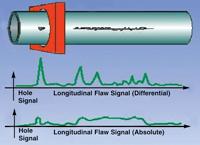
Figure 1A flawed tube passes through a through-coil sensor
Placement
Detection units pick up two types of information: the test signal and background noise (generated by vibrations caused by the tube-making equipment). A valid test result depends on a strong test signal—one that isn't drowned out by the background noise. The difference between these two types of information is expressed as the signal-to-noise ratio. The ideal location for an eddy current sensor is one where the noise is minimal to moderate.
Tube producers can test the material at any stage, from parent material to finished product. Testing the parent material cuts costs—it prevents processing defective material. Furthermore, tests carried out during this phase may be necessary to meet the requirements of controlled production per ISO 9000. On the other hand, testing the finished product generally is mandatory for copper tube (see Figure 3).
Testing the material at least twice, at the beginning and at the end of the manufacturing process, provides control over more than just the finished product; this arrangement allows manufacturers to monitor and control the manufacturing process itself. For example, if the quality of the raw material is consistent and the finished product shows an increasing number of flaws (decreasing quality), this indicates a growing problem, such as equipment in need of alignment, maintenance, or repair. Likewise, a change in background noise can indicate a need for maintenance. From that perspective, strategically placed test equipment can pay for itself by allowing tube producers to schedule maintenance and repairs when they are needed, thereby avoiding equipment failures and downtime.
One of the principal conditions for successful eddy current measurement is precise material guidance. The material must be guided centrally, both horizontally and vertically, in the measurement coil area. This requires placing the transmitter system between the horizontal and vertical straightening device, provided the rolls are adjusted correctly. To ensure precise guidance for vibration control and concentricity, a guide device with polished carbide-metal guide inserts has been developed specifically for testing copper tubes, in particular thin-walled copper tubes up to 35 mm (1.378 in.) OD.
Meeting Manufacturing Standards, Documenting Test Results
Tube producers should bear in mind that the testing standards stipulated by various agencies are minimum requirements. Manufacturing above-average-quality tube or pipe means using more stringent manufacturing procedures and testing specifications. For instance, to improve heat transfer in heat exchangers, many manufacturers decrease the wall thickness. As the wall thickness decreases, the sensitivity needed to detect surface flaws increases, often beyond the minimums specified by published standards.
It's not enough just to meet modern manufacturing requirements. Documen-tation and archiving of test results also are necessary for both quality management and liability (see Figure 4).
Increasingly Stringent Requirements
Many applications, such as chemical proccessing, heating, and cooling, require complex, high-quality nonferrous tube products. Many of these applications require tubes that are deformed substantially during processing—and therefore the manufacturing requirements are stringent and the testing requirements are sophisticated.
Inadequate testing leads to flaws and failures detected only in the end product, resulting in high losses. Flaws detected during installation or when the end product is put into service can lead to enormous claims for compensation in damages.
About the Author
About the Publication
subscribe now

The Tube and Pipe Journal became the first magazine dedicated to serving the metal tube and pipe industry in 1990. Today, it remains the only North American publication devoted to this industry, and it has become the most trusted source of information for tube and pipe professionals.
start your free subscription- Stay connected from anywhere

Easily access valuable industry resources now with full access to the digital edition of The Fabricator.

Easily access valuable industry resources now with full access to the digital edition of The Welder.

Easily access valuable industry resources now with full access to the digital edition of The Tube and Pipe Journal.

Easily access valuable industry resources now with full access to the digital edition of The Fabricator en Español.
- Podcasting

In this episode of The Fabricator Podcast, Caleb Chamberlain, co-founder and CEO of OSH Cut, discusses his company’s...
- Trending Articles
1
Team Industries names director of advanced technology and manufacturing

2
Orbital tube welding webinar to be held April 23

3
Chain hoist offers 60-ft. remote control range

4
Push-feeding saw station cuts nonferrous metals

5
Corrosion-inhibiting coating can be peeled off after use
