


Lasers loom larger in tube, pipe cutting
Ushering in a new era in tube design
 |
In today's manufacturing environment, 2-D lasers are the standard for cutting flat sheets and plate. Nearly everyone is familiar with laser technology's capabilities and speed for 2-D part processing. What may not be as well-known, however, is laser's 3-D capacity for mainstream processing of tubing and structural tubular components.
The assumption that 3-D lasers are highly specialized and applicable only for limited use could not be further from the truth. Five years ago 3-D lasers began being developed to process tubing and structural tubular components in one operation and with a high degree of accuracy.
With a better understanding of 3-D lasers and what they can offer, fabricators may be able to realize cost savings and lead-time reductions.
3-D Configurations
3-D lasers come in many different standard configurations to meet the varying needs of tube fabricators. For a fabricator who needs to fabricate flat parts and tubes, many traditional 2-D machines have been redesigned to include a table-mounted rotary chuck, as well as a multiaxis head configuration. For a fabricator producing high volumes of tubular parts, dedicated tubing lasers are most suitable.
These machines have two basic configurations—bundle-style and versatile-style. The bundle-style machines are designed to accept bundles of round, square, and rectangular tubes for high-volume batch processing applications. Versatile-style machines, for just-in-time (JIT), low-volume applications, are designed so that the material infeed uses V slots to transport the tubing into the machine chucks. Each V slot can be loaded with a different tube shape or diameter. Versatile machines also can process structural tubular components such as C channels or I beams.
Software Is Key to Improvements
The part programming software is key to the advancements in 3-D laser tube processing. The processing capacity and speed of today's personal computer and the advances in CAD/CAM technology have turned what was a complex and time-consuming programming process into a fast and easy-to-understand function. Most of today's 3-D laser cutting machines also come with programming software features that are unique to the machine's processing capabilities. Software packages offer part design, programming, collision detection review, and nesting. Design features can include 3-D solid model importing or part model development from 2-D CAD drawings.
Some of the software packages also include CAD modules that allow the development of tubing models from original concept or from 2-D paper drawings. Once the part model is brought into or developed by the software, programming can be completed by detecting the cut features and adding cutting technology to these features.
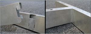 |
| Figure 1 Laser-cut tubes can be designed and cut with assembly aids such as weld prep bevels and slots and tabs that minimize or eliminate the need for welding fixtures. |
Cutting technology tables allow the program to set the cutting conditions based on the part features. Part features, including straight line, circular, corner radius, and bevel angles, may require different cutting conditions that the software can automatically select. Operators can revise cut conditions in the tables to get the best cut quality and cutting speeds for the various materials and wall thicknesses.
Another important feature included in some software packages is a collision detection routine. This feature allows a programmer to review a simulation of how the laser cutting head is positioned and programmed to cut the part through the entire cutting process before the program is sent to the shop floor. This process can eliminate potential machine damage caused by a collision of the cutting head with the part during the program cycle.
Finally, nesting routines also have been added to the software packages. Nesting allows a programmer to group parts that will be cut from the same material and cut them sequentially to maximize the "in-cut" time. More advanced packages allow the programmer to orient the parts to minimize the space between sequential parts, thereby reducing scrap. Often common-line cutting can be used when sequential parts have mating angles.
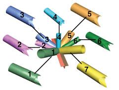 |
| Figure 2 Solid modeling and tight tolerances allow joints manufactured of multiple components to be designed and laser-cut to fit closely, improving joint fit-up, such as this patented roof truss node. |
Lasers Enhance Design Capabilities
Perhaps the most significant advantage of 3-D laser cutting is that parts can be designed with assembly aids such as weld prep bevels and slots and tabs. Slots and tabs allow two mating parts to connect before welding, thereby minimizing or eliminating the need for welding fixtures. The tabs and slots can be designed so that they are different sizes to prevent incorrect orientation and assembly (see Figure 1).
Solid modeling allows joints made of multiple components to be designed and laser-cut to fit closely. Manufacturing these joints using hard tooling would be difficult at best. Also, joint fit-up might not be as precise as laser-cut parts. Because the laser beam can be very small, features that could not otherwise be made now are possible (seeFigure 2).
Finally, some parts that had been assembled from many dissimilar components now can be made from just one piece of laser-cut tubing. For example, a tractor frame that had been assembled from several different components now can be assembled from one piece of tubing that has been laser-cut with tabbed and slotted features (see Figure 3).
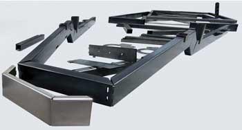 |
| Figure 3 Some parts, such as this tractor frame that had been assembled from several different components, now can be assembled from one piece of tubing that has been laser-cut with tabbed and slotted features. The bends are notched out and hand-bent into position. Small microtabs at the bottoms of the bends connect the tubes. |
Cost justification Is in Overall Process
Two common questions many fabricators ask when they consider laser tube processing for the first time are: "Why should I select laser tube processing over traditional methods?" and "How can I cost-justify the purchase?"
A reduction in the part processing time alone is not the sole cost justification for laser tube processing. Only an examination of the entire manufacturing process can show the true picture of the cost benefits. For example, part throughput can be increased with laser processing, because, typically, a tube can be laser-cut in one operation. In addition, the cost of hard tooling to support parts during traditional processing can be eliminated because laser processing does not place a physical load on the part. Non-value-added time for setup, material handling, and idle time associated with traditional manufacturing methods also is eliminated.
One cost consideration that often is overlooked when comparing different manufacturing methods is how downstream processes will be affected. Laser processing can affect how parts fit into assemblies and future design possibilities for new products. The accuracy and part repeatability of laser processing often reduces the amount of rework required in the final part assembly.
The final cost justification is in the cost of quality. The tight tolerances achieved with laser processing can reduce multiple setups and additional downstream operations otherwise required to ensure parts are manufactured to the designed tolerances.
Laser cutting technology, when used to maximize its benefits, can realize cost savings for fabricators competing in a changing world market. Laser processing can help meet the demands for smaller lots sizes and quicker turnaround times. In addition, it can offer new tools for designers. The possibilities are endless and limited only by one's imagination to use the technology.
| 3-D Laser Processing |
| In 2-D processing, the torch head moves along the X and Y axes (north to south, and east to west) across a plane. In 3-D processing, a torch head also moves up and down along a Z axis. Some machines have two additional axes so the head can rotate and angle for bevel cutting applications (five-axis). An additional rotary axis in the form of a chuck holds and positions the tube in the machine and rotates the tube around its centerline (six-axis). The same materials that can be processed with 2-D lasers—carbon steel, stainless steel, galvanized steel, aluminum, and so forth—can be processed with 3-D lasers. Wall thicknesses up to 7/8-inch steel, 1/2-in. stainless steel, and 3/8-in. aluminum can be cut. Bevel cutting reduces the wall thicknesses that can be cut, based on the bevel angle. 3-D lasers can cut up to a 45-degree bevel in carbon steel and 30 to 35 degrees in stainless steel. Round, square, and rectangular tubes, as well as structural tubular components and angle iron, can be processed, depending on the machine configuration. Machine capacities vary, depending on the design, but most standard machines can cut round tubes and pipes with diameters from 3/4 in. to 12 in.; material lengths up to 49 feet; and weights up to 40 pounds per linear foot. Accuracy also varies with machine design, but it is not uncommon to be able to hold feature tolerances in the range of ± 0.003 to 0.005 in. |
Peter Beck is 3D hardware and software product manager, Mazak Optonics Corp., 140 E. State Parkway, Schaumburg, IL 60173, 847-252-4500, pbeck@mazaklaser.com, www.mazaklaser.com.
About the Author
About the Publication
subscribe now

The Tube and Pipe Journal became the first magazine dedicated to serving the metal tube and pipe industry in 1990. Today, it remains the only North American publication devoted to this industry, and it has become the most trusted source of information for tube and pipe professionals.
start your free subscription- Stay connected from anywhere

Easily access valuable industry resources now with full access to the digital edition of The Fabricator.

Easily access valuable industry resources now with full access to the digital edition of The Welder.

Easily access valuable industry resources now with full access to the digital edition of The Tube and Pipe Journal.

Easily access valuable industry resources now with full access to the digital edition of The Fabricator en Español.
- Podcasting

In this episode of The Fabricator Podcast, Caleb Chamberlain, co-founder and CEO of OSH Cut, discusses his company’s...
- Trending Articles
1
Team Industries names director of advanced technology and manufacturing

2
3D laser tube cutting system available in 3, 4, or 5 kW

3
Corrosion-inhibiting coating can be peeled off after use

4
Zekelman Industries to invest $120 million in Arkansas expansion

5
Brushless copper tubing cutter adjusts to ODs up to 2-1/8 in.
