


Making a workhorse run
Getting the best performance from a vertical compression bender
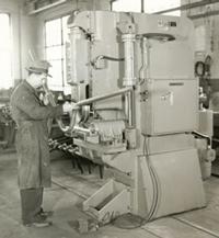
Figure 1 The use of vertical compression benders became widespread in the 1950s. A primary application was forming automotive exhaust pipes in high volumes. Photo courtesy of Pines Technology.
Vertical compression tube benders have been around for more than 50 years (see Figure 1). Historically associated with high-volume bending, these benders continue to play a role in production environments where parts have just one or two bends. Also known as press benders, they have stood the test of time mainly because of their speed and bend consistency. Depending on the application, a press bender can produce 900 bends per hour.
Bend quality is influenced mainly by the die setup. On a press bender, a ram die (punch) pushes through a bend, while two wing dies provide resistance, or cushion (see Figure 2). In addition to providing resistance, the wing dies keep the tube inside the punch die as it progresses through the bend.
A chief consideration in tooling setup is the wall factor, also known as the D/t ratio (the tube's OD divided by the wall thickness). When the wall factor is low (less than 30), the skill level needed to set up the tooling is not critical.
However, as the wall factor heads toward 50, the strength of the tubing (or lack of it) can affect bend quality. As the wall factor increases, the wing die pressure (cushion pressure), die alignment, and pinch pressure become increasingly critical for successful bending.
Wing Die Pressure
Wing die pressure, or cushion pressure, is directly related to how much resistance the wing dies apply to the tube as the ram die is pushing against them. If the pressure is too low for the application, wrinkles can appear. On the other hand, too much pressure combined with a high wall factor can result in several unwanted events (see Figure 3). First, during the bend cycle, the punch die might contact the wing dies. This can cause wrinkles. Second, the tooling might crush the tube beyond acceptable limits. This is more likely to happen when fabricating high-wall-factor tubing than low-wall-factor tubing.
Sometimes the application requires additional wing pressure. If the punch is already making contact with the wing dies, increasing the pressure will do nothing. In this case, modifying the wing dies is in order. Shaving 0.010 in. from the top of the wing dies may allow you to increase the cushion pressure. However, be careful not to shave too much off the top of the wing dies; this can lead to insufficient tube support, which can allow the tube material to flow between the punch die and wing dies.
Another point of concern when bending high-wall-factor tube is maintaining equal pressure in the wing dies. Uneven pressures can lead to asymmetrical bends.
Side-to-side Die Alignment
In general, wing dies that slide relative to the wing die holders are guided by bronze wear strips (see Figure 4). For applications with low wall factors, the alignment of the wing dies to each other and relative to the punch is important, yet not as critical as when the wall factor approaches 50.
As the wall factor approaches 50, it is necessary to hold the wing dies' lateral position relative to the groove in the punch die. This is because thin-wall tubes provide little side-to-side resistance to the bend tooling; if the dies aren't held in position, bend quality consistency decreases markedly. When bending a thicker-wall tube under the same conditions, tool alignment is not as critical.
Pinch in the Dies
You can have the right cushion pressure dialed in and perfect die alignment all around yet never achieve the needed bend quality because the tube grooves in the dies are cut incorrectly for the application.
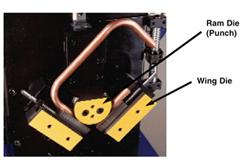
Figure 2 The alignment of the wing dies to the punch die is most important when bending soft or malleable materials, such as this 0.016-inch-wall copper tubing.
Grooves machined into the punch and wing dies are critical for successful high-wall-factor tube bending. The grooves' depth determines the amount of pressure, or squeeze, that the tooling exerts on the workpiece. Too little squeeze allows wrinkles to develop because the tooling doesn't adequately constrain the tube material. Too much squeeze can lead to gouge marks on the sides of the tube near the neutral axis.
The amount of squeeze is application-specific. In one application, 1 percent squeeze may work fine; another might require 8 percent.
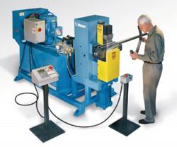
Figure 3 Too much cushion pressure can result in poor bend results even on thin-wall square tubing.
About the Author

About the Publication

subscribe now

The Tube and Pipe Journal became the first magazine dedicated to serving the metal tube and pipe industry in 1990. Today, it remains the only North American publication devoted to this industry, and it has become the most trusted source of information for tube and pipe professionals.
start your free subscription- Stay connected from anywhere

Easily access valuable industry resources now with full access to the digital edition of The Fabricator.

Easily access valuable industry resources now with full access to the digital edition of The Welder.

Easily access valuable industry resources now with full access to the digital edition of The Tube and Pipe Journal.

Easily access valuable industry resources now with full access to the digital edition of The Fabricator en Español.
- Podcasting

In this episode of The Fabricator Podcast, Caleb Chamberlain, co-founder and CEO of OSH Cut, discusses his company’s...
- Trending Articles
1
Team Industries names director of advanced technology and manufacturing

2
Orbital tube welding webinar to be held April 23

3
Chain hoist offers 60-ft. remote control range

4
Push-feeding saw station cuts nonferrous metals

5
Corrosion-inhibiting coating can be peeled off after use
