


Contributing Writer
 |
Eaton Corp. manufactures a patented end connector, called STC®, or Snap to Connect. It is a reusable connector designed for low-, medium-, and high-pressure applications. STC is a threadless connection that requires only hand assembly to connect and a simple release tool to disconnect. Twelve individual manufacturing processes are required to make a complete machined male connector half thatis brazed to a tube (see Figure 1).
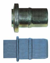 |
| Figure 1 The STC connector (top) is machined from barstock and brazed to tube. The FMSTC (bottom) has similar features that make it a direct substitute for the machined STC component. |
Because some of these process operations were thought to be more costly and less reliable than comparable forming methods, the company sought to develop an alternate connection method. Rather than manufacture a machined component, it wanted to eliminate the connector altogether and replace it with a tube end form that served the same purpose as the machined component for certain applications(see Figure 1).
Eaton Corp. worked with Wauseon Machine & Manufacturing Inc., Wauseon, Ohio, to come up with a suitable design. In some cases, such as connectors for O-ring face seal (ORFS), the female end is the better candidate for a forming operation. After evaluating the STC connectors, however, Wauseon determined the male end was the more suitable candidate for end forming.
The first step was to determine if it would be feasible to form a tube material and maintain the fit and function requirements of the joint. The material for the new FMSTC, or Formed Male Snap To Connect, is low-carbon steel tubing that is welded, drawn, and annealed.
Wauseon recommended using this material because it had an optimum set of properties for this application. The steel's low carbon content contributes to its formability, and being welded rather than extruded keeps the cost down. However, welded tube does have variations in its OD, so drawing the tube through a die enhances the dimensional consistency needed for making reliable, leakproofconnections. Finally, annealing reduces the hardness caused by the welding operation along the weld seam and relieves stresses in the material, both of which enhance the tube's formability.
The second step was to develop the progression of the end form with the aid of CAD solid-modeling software. Modeling the machined connector first, paying particular attention to how it was designed and toleranced, facilitated designing a process that would form the tube to the same dimensions.
The third step involved a failure modes and effects analysis (FMEA). An FMEA is a process that numerically ranks the severity, occurrence, and detection of potential problems with the manufacture of the product. A risk priority number (RPN) of a potential defect in producing the part comes from that ranking and then is assigned. When the RPN is too high, a design deviation or an alternateprocess must be considered.
The FMEA revealed that some machined features, such as sharp corners and small radii, would present some potential failure modes for an end forming operation. Because one manufacturing method usually is not a perfect substitute for another, engineers and project managers know that some part features might have to be modified slightly when changing to a new manufacturing method.
Another failure mode resulted from variations expected in different lots of tubing. Tubing from one mill run can vary from that of another in tensile strength, yield strength, elongation, and hardness. Furthermore, commercial tolerances of the OD and wall thickness can lead to part variation, making it difficult to maintain close tolerances when forming some of the features that otherwisewould be machined.
The end form concept was based on using a ram-type end former and two separate sets of tools. The 12 manufacturing steps needed for STC were reduced to seven steps at this stage of FMSTC development.
After approval of the concept design and FMEA, the progressions were used to design the tooling. Material flow characteristics and a maximum expansion percentage were evaluated and distributed over each hit of the progression, which led to the development of a corresponding punch.
A CAD solid model of each progression allowed the designer to model the forming punch around each progression. Clamp blocks that hold the tube were designed for minimum clamp length. This minimized the longitudinal tube reduction in the area behind the end form, which aids subsequent operations such as forming or bending before the tube is installed in its final application.
Tooling must be both manufactured and inspected to close tolerances. It is imperative that tools can be reproduced with confidence because they are perishable items that must be replaced periodically.
The initial part tryout and inspection revealed that some tooling modifications were necessary. After the modifications were made, a set of samples were manufactured and sent to Eaton for review. Wauseon and Eaton determined that a statistical study of all characteristics on 100 sample pieces would be required before any further development or testing could take place. The results of thecapability study confirmed the dimensional tolerance failure in some areas discovered by the FMEA.
The primary problem was thought to be process-related. Locating the part in two separate operations was contributing to part variation, even though the part was located to a fixed stop each time. The bead diameter and location varied because the end was not exactly perpendicular to the centerline of the tube after the first forming operation and then it was relocated on a different spot in thesecond operation.
 |
| Figure 2 The end form tooling includes primary clamp dies, auxiliary clamp die, and a finish punch, all shown here in a section view. The end forming process produces an FMSTC end form in a single operation. (The punch, which forms the bead on the tube, is not shown.) |
The solution was obvious. The tooling and the two operations would have to be combined to produce a complete part in a single operation. This would require a special set of clamp dies and an auxiliary lockup, which is a machine option. Using the same basic punch design, the first-operation clamp dies would close; the subsequent ram strokes would form the shape previously produced in the firstoperation; and with the part still held in the machine, the auxiliary clamp dies would close, followed by ram strokes that make the final form (see Figure 2).
Further minor modifications were made throughout the tryout, development, and completion of tools for the initial tube diameter and other nominal sizes that followed. Capability studies and product testing had favorable outcomes. Throughout the final development, end forms made on different lots of material displayed slight variations. A method of adjustment was built into the punches tocompensate for the tubing variations, and a successful runoff followed.
The final design eliminated one of the forming steps from the process. FMSTC can be made in six steps, a 50 percent reduction from the 12 process steps formerly required for manufacturing an STC male end. "The time required to form FMSTC is one- fifth of that required to machine and braze the male STC to a tube," according to Paul R. DeWitt, senior project engineer of Eaton Corp.
Furthermore, FMSTC requires less overall operator skill. "The skill level required for the FMSTC forming operation is less than that for the machining operations but more than the skill level required for brazing," DeWitt said. "The key here is that FMSTC has fewer operations as a whole, so the total skill level required is significantly less than for STC."
Because FMSTC is an integral part of the finished tube, leak paths are not introduced as is common after brazing a connector to the tube. It provides a more reliable product for myriad applications such as power steering unit return lines, air-conditioning applications on mobile equipment, and engine fuel lines.
Eric Patty is president of Wauseon Machine & Manufacturing Inc., 995 Enterprise, Wauseon, OH 43567, 419-337-0940, fax 419-335-1640, epatty@wauseonmachine.com, www.wauseonmachine.com. Wauseon Machine & Manufacturing designs and builds toolingand standard and custom equipment with an emphasis on tube fabricating.
Keith Wiechers, tooling project engineer of Wauseon Machine & Manufacturing Inc., contributed to this article.
Eaton Corporation, Eaton Center, 1111 Superior Ave., Cleveland, OH 44114-2584, 888-858-5658, stc@eaton.com, www.eaton.com.

The Tube and Pipe Journal became the first magazine dedicated to serving the metal tube and pipe industry in 1990. Today, it remains the only North American publication devoted to this industry, and it has become the most trusted source of information for tube and pipe professionals.
start your free subscription
Easily access valuable industry resources now with full access to the digital edition of The Fabricator.

Easily access valuable industry resources now with full access to the digital edition of The Welder.

Easily access valuable industry resources now with full access to the digital edition of The Tube and Pipe Journal.

Easily access valuable industry resources now with full access to the digital edition of The Fabricator en Español.
In this episode of The Fabricator Podcast, Caleb Chamberlain, co-founder and CEO of OSH Cut, discusses his company’s...


