


Contributing Writer
 |
Producing holes in tubing with punch press tooling can be divided into two main processes: punching and piercing (see Figure 1).
Tube piercing is different from traditional hole punching in that a die is not employed on the underside of the material. Instead, external guides encapsulate the tube to maintain consistency in its outside dimensions.
Once the guides are fully engaged around the tubing, a punch that runs through the ID of the top guide is pressed into the wall of the tube. Thus, before punch breakthrough is achieved, the material is stretched as far as its elasticity allows, producing a dimple around the hole.
 |
| Figure 1 The different methods of punching and piercing produce different hole conditions. |
Many factors affect the size and shape of the dimple, including hole size, tube diameter, material properties, and material thickness. For example, a 0.25–inch–diameter hole in a 1.00–in. by 14–gauge–wall mild steel tube will produce a moderate dimple. However, if the hole size is increased or a lighter–gauge or more elastic material is used, the dimple size likely will increase. If the hole diameter is relatively large compared to the tube diameter, the tube walls will help support the material on two sides of the hole, resulting in an elongated dimple. Typically, these factors cannot be controlled; they are contingent on the design of the part or finished product.
Another factor that affects dimple size-one that can be controlled-is the design of the punch tip. Introducing a shear angle to the punch tip reduces the force requirement and therefore usually results in a smaller dimple. Experimenting with straight, rooftop, concave, or pointed shear angles can help produce the desired dimpling effect. The shear angle must run parallel with the length of the tube, and not against it, to produce maximum benefits.
 |
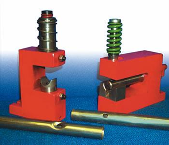
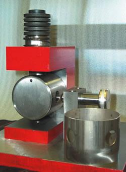
| Figure 2 With interchangeable guides, a tube pierce tool can be used for either a single- or double-dimple operation. |
Three standard types of tube piercing are:
Single-dimple piercing, which is the most common, is the process described previously.
Double-dimple piercing works much like the single–dimple operation, except that a second punch is introduced in the lower guide. While the top punch is advancing into the tube, the entire guide assembly, including the encapsulated tube, is forced down over the second punch, which remains stationary. Either of these punches can be removed to change hole size or to change to a single–dimple operation. The guides also are interchangeable so that a single station can be used to accommodate multiple tube sizes (see Figure 2).
For applications that require a dimpled hole on one side of the tube and a clean hole on the other, straight–through piercing is recommended. As with the single– and double–dimple operations, the tube is clamped in place by upper and lower guides. The difference in this case is that the lower guide has a die button. This enables the punch, after it pierces through the top wall, to continue through the tube and punch a dimple–free hole on the bottom wall.
Although this type of hole offers advantages for some applications, some factors must be considered.
One necessary condition of this type of operation is that the bottom hole is punched with the slug from the top hole still pressed against the face of the punch tip. Because of this the bottom hole may be slightly burred, and punch life may be reduced. (If a fairly significant shear angle is used, the slug sometimes remains attached to the top wall of the tube.)
A second necessary condition of straight–through tube piercing is that the straight before radius (SBR) of the punch tip must be at least as long as the diameter of the tube. This condition also may result in a shortened punch life, especially if the punch tip has a small diameter.
A third necessary condition is the size of the stripping spring. The length and strength of the spring required to strip the punch can make it impractical to pierce straight through tubes larger than 1 in. in diameter.
When a clean (dimple–free) hole is required in a tube, a hole punching operation is used. Instead of external guides encapsulating the tube, a mandrel is used internally to support its shape. The mandrel contains a die button that makes this procedure similar to standard flat–material hole punching operations.
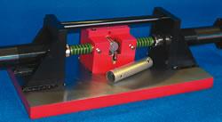
With this tool, the punch is extended, compressing the material against the mandrel and ultimately breaking through into the die, which acts as a cutting surface. Because the mandrel is supporting the inside of the tube, the dimpling effect of piercing is eliminated (see Figure 3).
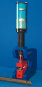 |
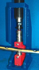
| Figure 3 A dedicated single-punch mandrel station is powered by an air-oil cylinder to produce clean, dimple-free holes in tubing. |
This operation introduces more variables that need to be considered. First, the mandrel size is critical. To produce a clean, dimple–free hole and to maintain the consistency of the tube shape, the size of the mandrel must be as close as possible to the ID of the tube. Typically, a mandrel should be 0.001 in. smaller than the smallest ID that is allowed by the production tolerances of the tubing.
This in turn introduces two more factors. Because the mandrel is such a precise fit, the ends of cut–to–length tubing must remain consistent and burr–free. In addition, if the tube has a weld seam, the mandrel will need to be relieved with either a slot or a flat to accommodate the seam. Of course, the more material that is removed from the mandrel, the weaker it becomes, so this should be minimized.
The second important variable is mandrel strength. The incorporation of the die hole and slug relief into the mandrel necessarily involves the removal of material. The larger the hole being punched relative to the size of the tube, the weaker the mandrel becomes. This limits the size of the hole that can be punched, but there is no simple formula to determine what that limit is.
Many factors play a role in determining the hole size limit for a given tube: whether the tube is round or square, material strength, wall thickness, and shear angle, to name a few. A rough guideline is that the hole size should not exceed 50 percent of the tube ID; however, in some successful extreme applications, this ratio has been as high as 75 percent. Often the best guides when considering whether extreme applications are suitable are experience, trial and error, and common sense.
In most cases a tube support and a stripper plate should be used to prevent mandrel deflection during the punching or punch retraction processes. In applications that use a large–diameter, short mandrel (typically 1 in. or less), these features may not be necessary. In applications in which a small punch diameter is used, the stripper plate can add extra support and guidance for the punch. This usually is required only in extreme conditions, such as when using a very small punch diameter in a straight–through punching application.
 |
| Figure 4 A single-punch mandrel tool can produce multiple holes with a pickup pin. |
Like piercing, tube punching can be subcategorized into:
Single punching has already been described. When a single punching station produces a through–hole or multiple holes, a pickup pin can be employed to locate the tube for subsequent hits by picking up from previously punched holes (see Figure 4).
When speed is important in through–hole applications, as often is the case in large–quantity production runs, straight–through or double punching may be more efficient than relocating.
Straight–through punching works much the same as straight–through piercing and is subject to the same maintenance and tool wear considerations. In this case the punch, after producing the hole in the top wall of the tube, continues through the mandrel to punch the bottom hole by compressing and penetrating the bottom wall of the tube against a die button in the support block.
 |
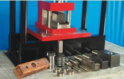
| Figure 5 A double-punching station uses two air-oil cylinders to produce clean, dimple-free through-holes. |
Although straight–through punching is a viable option, because of the increased tool wear and maintenance, double punching often is used instead. Double punching uses two opposing horizontal punches. The process is performed in a conventional press with a cam action die or with a custom setup of opposing hydraulic or air–oil cylinders. The cylinders are cycled simultaneously, producing the through–hole in one cycle. The slugs either fall through a slug chute in the bottom of the mandrel or are blown out a relieved section in its front.
With this process, using short–stroke cylinders eliminates pinch points, reduces the tool wear and maintenance problems, and produces cycle times as low as one cycle per second (see Figure 5).
The method chosen to make a hole in tubing depends on many factors:
 |
| Figure 6 On dedicated punching stations, quick tooling changeover can accommodate various tube and hole sizes, both round and shaped. |
Todd Bryson is an engineering manager with Multicyl Inc., 640 Hardwick Road, Unit 5, Bolton, ON, Canada L7E 5R1, 905-951-0670, fax 905-951-0672. Multicyl manufactures a patented line of air and oil pressure intensifiers used for many pressworking applications, including hole punching, notching, and assembly of flat sheet metal and tubing.

The Tube and Pipe Journal became the first magazine dedicated to serving the metal tube and pipe industry in 1990. Today, it remains the only North American publication devoted to this industry, and it has become the most trusted source of information for tube and pipe professionals.
start your free subscription
Easily access valuable industry resources now with full access to the digital edition of The Fabricator.

Easily access valuable industry resources now with full access to the digital edition of The Welder.

Easily access valuable industry resources now with full access to the digital edition of The Tube and Pipe Journal.

Easily access valuable industry resources now with full access to the digital edition of The Fabricator en Español.
In this episode of The Fabricator Podcast, Caleb Chamberlain, co-founder and CEO of OSH Cut, discusses his company’s...


