Understanding benders and bender applications
Matching them up for optimal output
Tube bending methods vary in complexity as much as any fabricating process does. At the simple end are applications that involve tubing so small and bends so simple that bending by hand is a suitable process. Manual bending machines and dedicated hydraulic or pneumatic benders occupy the middle ground, and fully programmable benders that play a central role in automated bending cells are at the sophisticated end of the spectrum.
Understanding how bending demands have changed over the decades and how bender manufacturers have responded are two key components in selecting the optimal bender for your particular application.
Manual Bending for Automotive Applications
Until the early 1980s, many leading automotive companies and automotive suppliers relied on manual processes for bending brake lines and fuel lines—workers bent the lines by hand over wooden gauges or at best used manual lever-type benders. The bending result was inconsistent and influenced by many variables, such as the operator's skill level, because the bending speed affected the final tube shapes.
Using a conventional bending machine for this application usually failed because when bending line lengths more than 6 feet (2 meters), the operator had to support the line by hand during the bending process. Otherwise, the bending motion would cause the tube to whip. Accurate bending required human assistance.
CNC With Automation. An innovation in 1985, the CNC, dual-head bending machine for bending fuel lines and brake lines, changed all that. The process divided the line length, up to 20 ft. (6 m) into two halves. This reduced the free line length. However, it did not eliminate the whipping effect; the machine's processes—bending, turning, and transporting the line—still caused this problem.
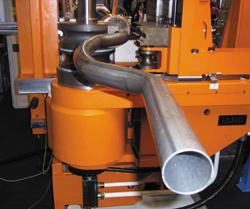
The solution was to stop transporting and turning the tube. A new machine style rotated the angle turning unit with the bending head around the pipe and moved axially along the tube's length. The spatial turning of the pipe and the intermediate lengths between the bends meant that the machine did not move the pipe and so it was not subject to the whipping effect. The only movement came from the actual bending process.
The dual-head function allowed the number of bends to be split between two sides that function independently of one another. The most favorable case is making two symmetrical finished products from a single length of raw tube.
The machine already reduced cycle time compared to manual bending; if the application was symmetric, automation reduced the cycle time further. In some cases, it cut it in half.
The dual-head machine does, however, require a minimum pipe clamping length. Ideally, the clamping length is in the middle of the bends and is at least 7.875 in. (200 mm). In some cases, 4.5 in. (115 mm) is sufficient.
Bending Short Lengths. To bend tube with shorter clamping lengths with a straight pipe length of up to 6.5 ft. (2 m), a single-head bending machine was developed that operates on the same bending principle, except that for the straight lengths the machine moves the pipe axially. However, this does not contribute to a significant amount of the ensuing whip effect.
Dedicated Bender or Programmable Bender?
Flexible, CNC bending machines quickly caught on in Germany, yet single-purpose machines (power benders) were employed in other countries, particularly in the U.S. and Canada. This type of machine bends just one tube or pipe size with a specific contour. The bending movements usually are performed by pneumatic cylinders; each cylinder and each tool element produces just one precisely defined bend. The great advantage of these machines is that the investment costs are far lower than for the flexible, programmable, CNC machines. In some cases, they also are faster. However, with the slightest modification in the part—and this is a frequent occurrence during the development phase—a single-purpose machine has to be scrapped and replaced by a new machine.
The current trend in the automotive industry is toward more niche vehicles and many variations, each with different performance requirements, and thus ever-smaller volumes. This forces fabricators to procure new power benders more frequently. Another result is that many suppliers are not able to bid on certain line lot sizes. In view of this trend, producers are considering more closely the use of flexible, automated, CNC bending machines.
The history of the use of power benders means, however, that the expectations with respect to speed, repeatability, and fault frequency are high. In bending, zero tolerances are expected, cycle times must be optimized, and even the slightest operator error must be prevented. These demands do not represent an insurmountable task. Rather, they represent options that further optimize bending machines.
Raw Material
Apart from the actual bending quality, two further points are important for good bent pipe quality.
First, it is always necessary to use tubes that meet the specifications for the finished product. This might seem obvious, but in some cases the incoming tubes differ little if at all in their appearance. Although they are marked, after they are unbundled, various lots of tube or pipe can get mixed up. Manufacturing a single part run from raw material that varies can result in parts that don't meet specifications.
Second, the pipe quality must be optimal.
The Latest Step: 100 Percent Quality Control
A common demand these days is 100 percent quality control on the bending machine. A typical brake line is complex enough to justify integrating a high-resolution camera with a digital control system that has a teach-in function for specific dimensions and acceptable tolerances on a particular line.
In the case of a brake line, inspection criteria include:
- Is the nut fitted?
- Is the correct nut fitted?
- Is the nut fitted in the correct orientation (not backward)?
- Does the line have the correct flange?
- Is the flange diameter within the tolerance?
- Does the insulation start at the right point?
The machine can be programmed to stop automatically and generate an error message if it rejects more than two parts in succession. The incoming tubes must then be checked to determine whether a wrong bundle was loaded.
Another problem is that one manufacturing cell processes a variety of parts, and they vary in length. The cameras are mobile and travel with the magazine when it moves to verify the correct stock length is loaded when changing from one part number to another.
The cameras can be linked to the side walls of the magazine together with the necessary lighting unit and are then positioned automatically together with the magazine. This eliminates the need for manual adjustment or focusing. This means that the cameras have to "learn" the tolerances and dimensions for the part only once and can later call up the stored data.
Twenty-two sensor evaluations can be performed on each side. One main sensor serves as the reference sensor for all the others, so that in the event of a shift in position, all the sensors automatically reposition relative to the main sensor.
The quality process goes further. The bending machine contains various interfaces for pipe measuring systems. The processor feeds the measurement results back into the bender's CNC. If the data deviates from the nominal data, the system automatically corrects the bending or turning angle. The set-point data is based on either a previously measured specimen part or on stored Cartesian coordinates that also can be input directly from a CAD system.
Tube and pipe producers that further process tube and pipe can use such a system for carrying out a variety of evaluations, such as how many pipes per type are scrap, the most frequent cause of scrap generation, and on which pipe type this occurs most frequently. It thus provides a means for continuous quality improvement.
About the Author
About the Publication
subscribe now

The Tube and Pipe Journal became the first magazine dedicated to serving the metal tube and pipe industry in 1990. Today, it remains the only North American publication devoted to this industry, and it has become the most trusted source of information for tube and pipe professionals.
start your free subscription- Stay connected from anywhere

Easily access valuable industry resources now with full access to the digital edition of The Fabricator.

Easily access valuable industry resources now with full access to the digital edition of The Welder.

Easily access valuable industry resources now with full access to the digital edition of The Tube and Pipe Journal.

Easily access valuable industry resources now with full access to the digital edition of The Fabricator en Español.
- Podcasting

In this episode of The Fabricator Podcast, Caleb Chamberlain, co-founder and CEO of OSH Cut, discusses his company’s...