Vice President
Tube and pipe producers are a demanding breed. They have to be. With line costs up to $15,000 per hour, unexpected downtime can destroy the bottom line. Keeping the line up and running is critical, and in tube and pipe production shops everywhere, one important concern is the cutoff area.
Until recently tube producers relied on friction and high-speed steel (HSS) saw blades for circular sawing cutoff lines. Friction blades serve a purpose in the tube and pipe industry, and some companies continue to use them for existing and new installations. They are low-cost items that operate at high speeds and do not require a lot of sawing knowledge to use.
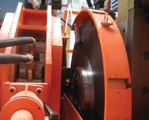
That said, friction saws do have disadvantages. Safety is one concern. Friction blades are large in diameter, and depending on the rotational speed, the linear velocity at the tips of the teeth can exceed 180 feet per second (FPS). Breakage at such a speed can cause severe damage to the machine and its surroundings. Also, they tend to generate quite a bit of noise and heat (see Figure 1). In many cases, extra precautions, such as sound attenuation cabinets and protective shields, must be in place to conform to OSHA regulations. The service life of friction blades can be inconsistent, and therefore can cause unexpected line stops and tool changes.
Advances in blade geometry and coating technology have made tungsten carbide-tipped (TCT) circular saws a viable option. TCT blades typically are smaller in diameter and run at lower peripheral speeds than friction blades. Blade breakage is less an issue, and if a crash does occur, flying debris is a smaller hazard. Also, TCT blades run quietly. Sound attenuation cabinets are not necessary.
Because TCT saws draw a chip at the workpiece, material removal is clean, precise, and repeatable throughout the cut (see Figure 2).
The most important advantage of TCT circular saws in tube production is durability. Depending on the tube size and workpiece material grade, a TCT blade can last up to four shifts.
Switching to TCT blades isn't as simple as installing new blades on an existing saw. TCT blades require a more sophisticated equipment setup than
friction blades do. Five tips can help you get started in planning the switch.The ability to manipulate the blade speed and feed rate is critical to both line speed and blade life. The speed doesn't refer to revolutions per minute (RPM), but the peripheral speed of the blade, which is measured in feet per second or meters per minute. The peripheral speed = RPM x pi x blade diameter.
The feed rate is measured in inches per tooth or millimeters per tooth. Most of the technical work associated with tuning a flying cutoff setup deals with manipulating these variables to optimize every application.
During the testing process, it is a good idea to start with the manufacturer's suggested blade speed and feed rate and tune the saw by changing the feed rate. The key is to make changes that affect the chip load by a maximum of 0.001 in. Note that the blade's speed, the number of teeth, and material feed rate, and the chip load are related to each other by the following formulas:
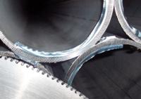
Figure 1 Friction sawing usually generates heat that softens the workpiece, resulting in a burr which must be removed before shipping the product.
RPM = Feed rate / (Number of Teeth x Chip load)
Feed rate = RPM x (Number of Teeth x Chip load)
Chip load = Feed rate / (RPM x Number of Teeth)
The last formula is useful for demonstrating appropriate changes for optimizing the sawing process. A slight increase in the feed rate or decrease in the blade speed results in a chip load change of approximately 0.001:
Initial Setting: Chip load = 15 FPM / (25 RPM x 60 teeth) = 0.01
New Setting 1: Chip load = 16.5 FPM / (25 RPM x 60 teeth) = 0.011
New Setting 2: Chip load = 15 FPM / (23 RPM x 60 teeth) = 0.0109
Decrease the chip load for harder, heavier materials; increase the chip load for lighter, softer materials. The sound of the sawing process is a good guide. Tune to the point where you hear a smooth, consistent sound.
Using TCT blades requires more than a few formulas. TCT sawing is an advanced process that requires a specialized line technician. If you plan to run TCT, make sure you have access to a technician who understands the dynamics of process control, including proper chip load, peripheral speed, and feed control. The right person should be able to help you make improvements, establish parameters, and adapt those parameters for difficult jobs.
Figure 2 Tubes cut by a TCT blade exhibit a clean cut. In most cases, the workpieces do not require deburring.


The Tube and Pipe Journal became the first magazine dedicated to serving the metal tube and pipe industry in 1990. Today, it remains the only North American publication devoted to this industry, and it has become the most trusted source of information for tube and pipe professionals.
start your free subscription
Easily access valuable industry resources now with full access to the digital edition of The Fabricator.

Easily access valuable industry resources now with full access to the digital edition of The Welder.

Easily access valuable industry resources now with full access to the digital edition of The Tube and Pipe Journal.

Easily access valuable industry resources now with full access to the digital edition of The Fabricator en Español.
In this podcast episode, Brian Steel, CEO of Cadrex Manufacturing, discusses the challenges of acquiring, merging, and integrating...