


President
We always have some confusion at our house concerning desserts. My wife claims that I like only two kinds of pie: hot and cold. Well, she is mostly right. My favorite is cherry, and I love it served either hot or cold. Here's our family recipe—you be the judge.
Grandma's Cherry Pie
Ingredients:Directions
A completely different type of confusion clouds two important homonyms: pie and pi. Pie is an English word for a baked dish with fruit or meat and an upper crust, lower crust, or both. Pi is the English spelling for p, the 16th letter of the Greek alphabet and a symbol for the ratio of a circle's circumference to its diameter. A mathematical constant, its value is approximately 3.14159.
Why all the talk of pie and pi? A reader recently asked how to determine if a tube mill has been set up properly. Part of the answer is to use a Pi Tape®, a measuring tape that has a vernier scale for accuracy. Named for mathematician Pierre Vernier, a vernier scale is a short, graduated scale that slides along a longer graduated instrument and indicates fractional parts of divisions. It's an ideal tool for measuring girth, or the distance around the outside of an open profile (such as in the fin passes) or the finished tube (as it is finished in the sizing passes).
Your spouse might tell you if you eat too much pie you will have a change in girth measurement, which is measured in inches and determined by your belt size, but that's another story.
OK, back to the question of determining a good mill setup. Just as a good cook knows the way around the kitchen and always follows the recipe, a good mill operator knows the mill and uses the setup chart and mill records. The mill records should include settings for every tube diameter and wall thickness produced on the mill, roll condition, and setup charts.
The roll setup chart supplied by the roll tool producer gives a starting point for the roll tooling flange gaps. It's a starting point because the flange gaps are specified for new roll tooling. The flange gaps are different for worn tooling. When you are setting up tooling that already has been used to produce 1 million feet of tube, how do you compensate for tool wear? You do this by measuring the tube's girth at several stages along the tube mill.
Calipers, micrometers, and tapes are commonly used measurement tools. Knowing their capabilities and limitations can help you select the right one for the job.
Choosing a Measuring Device. Diameter measurements taken with calipers or micrometers generally are accurate to 0.001 inch, but the measurement is valid only for the distance across the two points selected. Tube usually is not perfectly round, so you need to take several readings and average the diameter measurements. When you have to interpolate between multiple measurements to find the average diameter, you can be misled into thinking you have accurate results when, in fact, you don't.
 |
|
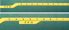
A measurement tape has a measurement section and a vernier section (top). These two scales are used together to measure the girth of an object to an accuracy of three decimal places. This example indicates 0.531 in. (bottom). The first two digits are determined by reading the 0 on the vernier scale, which is just to the right of the third line to the right of the 5, which indicates 0.53 in. To determine the third digit, find the vernier line that most closely aligns with any measurement line. In this case, the vernier line 1 directly aligns with a measurement line, so the three digits are 0.531. |
However, you can avoid the need to take multiple diameter measurements and prevent interpolation errors by using a special measuring tape that measures girth directly. Only by using a girth measurement tape can you judge the quality of your work precisely.
Using a Girth Measuring Tape. Girth measuring tapes with vernier scales are available for measuring tube from 0.250 to 144 in. OD in both inches and metric.
A typical measurement tape is suitable for tubes from 0.250 to 2.0 in. It has a measurement section and a vernier section. When used together, these sections can measure girth to an accuracy of ± 0.001 in.
The measurement section has large numerals that indicate inches, small numerals that indicate tenths of inches, and lines that indicate hundredths of inches. The vernier scale has lines labeled with numerals to indicate thousandths of inches. Note that girth measuring tapes measure units of pi and indicate either inches or millimeters.
To use the tape, wrap it snugly around a tube. The 0 on the vernier scale determines the measurement to two decimal places, and the vernier scale itself determines the third decimal place. In Figure 1, the 0 on the vernier scale is to the right of the small numeral 5 (the tenths of inches scale), which indicates 0.5 in.; it also is just to the right of the third line (the hundredths of inches scale), which refines the measurement to 0.53 in. To find the third decimal, look at the vernier scale to determine which line on it most closely aligns with any line (it doesn't matter which one) on the measurement scale. In this case, the vernier 1 is almost perfectly aligned with one of the lines on the measurement scale, so the third digit is a 1. Therefore, this tube measures 0.531 in. in diameter.
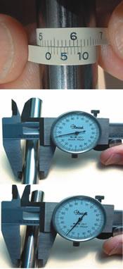 |
| Figure 2 A tape gives a direct measurement of girth. A caliper provides a measurement between two points, so the circumference must be calculated. Furthermore, caliper readings can be misleading. For example, a tube that actually measures 0.531 in. in OD (top) can appear as 0.542 in. (middle) and 0.517 in. in OD (bottom). The average of the two caliper readings is 0.5295 in., not 0.531 in. |
Comparing a Girth Tape Reading With a Caliper Reading. A girth tape measures girth accurately in one measurement (see Figure 2). A caliper must be used several times at several orientations around the tube's diameter, and the readings must be averaged. Even after taking two readings, though, the caliper might not produce an accurate measurement. For instance, a 0.531-in.-OD tube might appear to have an OD as small as 0.517 in. or as large as 0.542 in. when measured with a caliper. The average of these readings is 0.5295 in. The girth measuring tape is therefore both quicker and more accurate.
Before going any further, let me repeat the mill mantra.
The tube mill is a toolholder. Roll shaft shoulders must be aligned. The tolerance from the top shaft to the bottom shaft must be ± 0.001 in. The tolerance along the length of the mill (pass to pass, from breakdown through sizing) must be no more than 10 percent of the minimum gauge and not more than 0.005 in. All shafts, driven and idle, must be parallel to one another and not worn or bent. Bearings must be sound and shafts must rotate without runout. If you have replaced roll shafts, bearings, stands, or seals, stop now and align the mill before proceeding. Trying to run a misaligned mill doesn't prove how good you are; it merely shows how much time and money you can waste trying to compensate for using a misaligned machine.
You might have noticed that roll flange gaps are not mentioned in the tube mill mantra. As long as the flange gaps are not too large (not more than one-third the minimum gauge) and therefore permit material extrusion, they are not important. In fact, flange gaps can be nonexistent (in other words, the flanges can touch each other). Flanges will touch each other when the roll tooling is worn out so this is a service life issue.
I can already imagine the objections, protests, or at least intense disagreement from every roll designer in the tube and pipe industry, but hear me out. I recommend recording the flange gaps at the end of each run. Further, I recommend that you use the flange gaps for the setup and to ensure the roll shafts are parallel, but not to produce the finished tube. The point here is that after proper girth settings are determined, they do not change for that OD, regardless of wall thickness changes or increased tooling wear. Relax and read on!
 |
| Figure 3 Typical girth measurements for a 2-in.-OD, 0.105-in.-wall-thickness tube. The initial strip width is 6.164 in. The circumference at the OD is 6.2832 in.; 5.9533 at the neutral axis; and 5.6235 in. at the ID. After the girth readings are established, they are the only readings necessary to verify a proper mill setup for subsequent installations of this particular set of roll tooling for manufacturing this product. |
Keeping in mind the need to achieve the required reduction in each pass, let's look at a typical roll setup and the measured diameter and girth. The following example is based on 2-in.-OD tube with a 0.105-in. wall (see Figure 3).
1. Measure girth just before the first fin pass. Girth increases here.
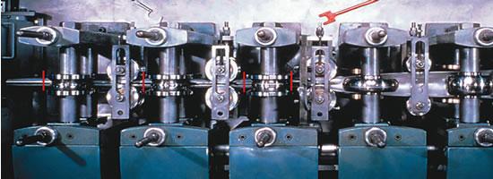 |
| Figure 4 To determine the girth of an open section of tube (before the seam is welded), measure it with a measuring tape; measure the width of the opening with a caliper; and find the difference. The vertical red lines show where to measure. |
Be aware that this growth is due not to strip thickness reduction but to bending in the breakdown zone. The inner fibers of the material are compressed while the outer fibers are stretched. The stretch imparted from forming increases the girth.
If the entering strip width is correct but you don't see the proper growth, check and adjust the breakdown section until you achieve the proper girth growth. Be careful here to keep roll shafts parallel, and don't close up the breakdown passes so much that they cause the strip belly or edges to thin. Too much closure force generally makes the strip edges longer than the belly of the strip and leads to welding problems. Form, but do not thin, the material. Watch for edge damage at the bottom corners of the strip. Worn tooling sometimes can thin or roll in the first 1/32 to 1/16 in. of the strip edge and cause welding problems. Back off the adjustment if this occurs, and let the fin passes correct the problem.
2. Measure girth after each of the fin, weld, and sizing passes. Girth decreases in these passes.
If you can't achieve the necessary amount of reduction, inspect the fin blades for wear and replace if needed.
Study the setup chart to learn the relationships between OD changes and girth. Your setup reduction percentages probably will be different from the example, but the important things to look for are consistent growth of the strip width entering the first fin pass and reasonably consistent reduction percentages in the fin and sizing passes. Try to balance the reduction so no one pass is doing more than its fair share of the work.
The reduction in the weld zone is essentially the weld upset loss to the OD and ID weld bead. The guideline for induction welding is to shoot for somewhere between one-third and one-fourth wall thickness loss. The loss in the example is a little more than one-third but is acceptable. You want to be sure to extrude enough material to achieve a sound weld.
After finding and recording the girth change settings (including the air gaps common in fin passes), you can duplicate them easily for the next run of that particular tube. Instead of taking multiple micrometer readings at each pass to confirm the setup for each shift, you simply need to check the girth progression to confirm that the process is consistent.
The only way to achieve repeatable results and reduce setup time is by paying attention to details and recording girth settings for the mill and roll tooling each time you run a product. Good records make the job of setting up the mill like using a cookbook!
If you still have questions about pi or pie, call me or send me an e-mail. I can provide further assistance with pi and setting up a tube mill. The only thing I really can't help you with is deciding if you prefer pie hot or cold.


The Tube and Pipe Journal became the first magazine dedicated to serving the metal tube and pipe industry in 1990. Today, it remains the only North American publication devoted to this industry, and it has become the most trusted source of information for tube and pipe professionals.
start your free subscription
Easily access valuable industry resources now with full access to the digital edition of The Fabricator.

Easily access valuable industry resources now with full access to the digital edition of The Welder.

Easily access valuable industry resources now with full access to the digital edition of The Tube and Pipe Journal.

Easily access valuable industry resources now with full access to the digital edition of The Fabricator en Español.
In this episode of The Fabricator Podcast, Caleb Chamberlain, co-founder and CEO of OSH Cut, discusses his company’s...


