


Contributing Writer
 |
The secret to developing successful roll tooling—whether for tube production or roll forming—and achieving maximum roll integrity is a simple but often overlooked notion: a comprehensive approach. Such an approach comprises five steps:
A designer's first task is to draw a part section that shows the:
The designer should pay special attention to critical areas, such as those where interference with mating parts may occur. Involving manufacturing managers and engineers early in the project may help to uncover troublesome areas and derail problems early.
When the drawing is finished, the designer sends it to the customer for review and approval. After receiving approval, the designer develops the tooling design. When laying out the flower, the tooling designer must consider the complexity of the profile, the customer's tube mill or roll forming machine, flexibility, vertical centers, horizontal centers, gearing, and positioning for cutoff. The designer may have to consider various combinations of these parameters for possible future revisions.
The next step in roll tooling design has two parts: developing the flower diagram and designing the profile. Several computer programs are available to assist the designer. Modern programs allow the designer to eliminate stretch, minimize stress and strain, and manipulate the flower with ease.
A complete discussion of flower diagrams and profile design is beyond the scope of this article. However, several important aspects include laying out the rolls, setup, and splitting the rolls.
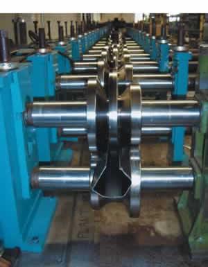
Laying out the Rolls. After finalizing the flower diagram, the designer begins surrounding the profile with steel, or laying out the rolls. A roll designer must flange the rolls properly. A general rule is if the material is flowing up, the flanges go up; if the material is flowing down, the flanges go down.
The designer also traps the material using metal stops, which prevent the material from wandering in the rolls and help eliminate camber from the incoming strip. Metal stops should allow for slitting tolerances as well. The design must also provide running clearance (extra room that allows the material to flow from pass to pass without being held back by the tooling) where necessary.
Setup. Two design considerations facilitate easier tooling setup: using feeler hubs and aligning material faces.
Feeler hubs are the gaps between the outer flanges of mating rolls. If the roll tooling is designed for 0.068-inch material, the designer should gap the feeler hubs at 0.068 in. This allows the setup person to use the material to set the gap.
Lining up the material faces allows a setup person to put a straightedge on the faces to check the shoulder lineup and to check the lineup from pass to pass. If the step-off is in 0.250-in. increments, this check may be done with a small tool bit or gauge block as the rolls get narrower from pass to pass. The designer indicates on the drawings any overforming of corners and the amount of step-up from pass to pass.
Splitting the Rolls. Roll splitting considerations include:
It is important that roll tooling conforms to specifications. With modern manufacturing processes, most companies can provide tooling within ±0.001-in. or tighter tolerance on diameters and widths and within ±0.0005-in. tolerance on the bores. In addition, the faces and diameters must not exceed 0.001 in. of total indicated runout (TIR). Grinding the faces, hard-turning the profiles, and grinding the bores true to the diameters after heat treating helps achieve these tolerances.
Proper inspection of roll tooling involves stacking the rolls on a granite plate using the correct spacers, lining up keyways, and putting arbors through the bores. The rolls are set to the proper gap by placing a corresponding gauge wire or pin between the flanges. Then the gauge wire or pin is used to verify that every gap, or clearance between the rolls, is as designed. Rolls that are not manufactured in pairs are checked on a comparator.
The roll finish must be free of turn marks. Additional polishing may be required if the appearance of the finished part is important. Polishing of tall flanges is always necessary.
The first step for setup personnel is to clean the bases, shafts, outboard stands, and housings. Shafts should be inspected, and any that are grooved, undersized, or chipped should be replaced. The shafts should be free of endplay and must be tight in the housings. The adjustments on both the inboard and outboard stands must be free and smooth.
A quick check of the datum plane can be accomplished by using a 6-ft. straightedge. For a precise check, a laser or a similar precision apparatus should be used. The datum plane must be in line and the shafts parallel. A straightedge is used to check each outboard pass between the shims and the shoulder, and these numbers are recorded. Then either the shoulders are moved or a set of permanent machine face alignment spacers are ground in to reflect a straight line.
Setup personnel then align the top shafts with the bottom shafts by using four rolls of exactly the same diameter and width. The shafts are adjusted so that they are parallel by using two rolls on the top and two on the bottom. Then, using a depth micrometer against the two inboard rolls, the setup operator checks the shoulders and records the numbers. As in the previous step, either the shoulders are moved or a set of permanent machine face alignment spacers are ground in to reflect a straight line.
The machine face alignment must be within ±0.002 in. top to bottom and ±0.005 in. station to station. Alignment lasers allow a much more precise alignment than a simple straightedge. The shoulders of the longest machines can be set to even tighter tolerances with a laser.
Eliminating or minimizing any problem with the incoming strip is essential. The strip width must be within the specifications as noted on the section drawing. A micrometer is used to check the thickness and a caliper to check the width.
The hardness, yield strength, and tensile strength must be as specified by the section drawing. Material suppliers usually provide this information on request. Excessive camber and slitting burr are not acceptable.
The setup operator should install the tooling, tighten the nuts, and parallel the shafts. Then he sets up the tooling according to the print and gauges it for the incoming strip. Using a mirror helps ensure proper lineup. Shoulders may be checked with a straightedge and gaps with a feeler gauge.
After the stock is run into the pass, the gaps at the shoulders (flanges) should be checked and fine adjustments made to remove any play in the vertical adjusting screws. This ensures that the rolls are set as the designer intended them to be set.
The cross section is checked one pass at a time by running out a 2- or 3-ft. section and checking for twist, slivers, and other defects. Doing this at every pass verifies proper roll lineup and eliminates potential problems at each pass.
The first goal of troubleshooting a roll tooling problem is to identify it. Saving a strip from every pass and comparing to the design enables analysis and makes it easier to determine where the problem lies.
Overbend. The tooling has markings that identify the passes that overbend the strip. These markings allow easy identification of overbending passes that may require adjustments and modifications.
Marking. Some marking can be reduced or eliminated by providing more running clearance, which improves the lead-in radius. Chrome plating the tooling or adding idler rolls before the pass that causes the defect also can help to reduce the amount of marking.
Other strategies include allowing the top drive to float (by disconnecting the drive gear if possible) or remaking the roll so that it runs on a hub and finds it own speed.
Dimensional Problems. Some dimensional problems can be fixed with shims. The first step is to analyze the product's dimensions to determine the pass that can be adjusted most easily to solve the problem, bearing in mind that the centerline of the tooling must remain constant. It may be necessary to cut the back spacer if the inboard side of the centerline is shimmed. The outboard bearing sleeves usually have enough play for some small shim adjustments.
Dan Mennecke is executive vice president of Comet Roll & Machine Co., 1775 Armitage Court, Addison, IL 60101, 630-268-1407, fax 630-268-1425, dmennecke@cometroll.com, www.cometroll.com. Comet Roll & Machine Co. manufactures roll tooling for the tube, pipe, and roll forming industries.

The Tube and Pipe Journal became the first magazine dedicated to serving the metal tube and pipe industry in 1990. Today, it remains the only North American publication devoted to this industry, and it has become the most trusted source of information for tube and pipe professionals.
start your free subscription
Easily access valuable industry resources now with full access to the digital edition of The Fabricator.

Easily access valuable industry resources now with full access to the digital edition of The Welder.

Easily access valuable industry resources now with full access to the digital edition of The Tube and Pipe Journal.

Easily access valuable industry resources now with full access to the digital edition of The Fabricator en Español.
In this episode of The Fabricator Podcast, Caleb Chamberlain, co-founder and CEO of OSH Cut, discusses his company’s...


