


Contributing Writer
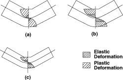
Figure 1A forming force that exceeds a material's yield strength results in plastic deformation, which holds the metal in the shape to be formed, and elastic deformation, which results in springback. The light crosshatched pattern indicates the areas of plastic deformation. The heavy crosshatched pattern indicates the areas of elastic deformation. Figure 1a shows the plastic and elastic deformation zones for a general-strength material; Figure 1b shows larger zones associated with a high-yield-strength material; Figure 1c shows that, compared with Figure 1b, a thinner-gauge material with the same yield strength has less plastic deformation and the same amount of elastic deformation. Because the relative amount of elastic deformation increases, however, springback increases.
High-strength materials such as high-strength, low-alloy (HSLA) steel have many advantages over standard-strength materials such as 1040 carbon steel and are widely used for structural components in many industries. Their greater strength on a pound-per-pound basis leads to material savings when fabricating structural components. Less material means less weight compared with a similar component made from a general-strength material. Weight savings is critical in many industries, particularly in the automotive industry.
However, forming high-strength materials is a challenge to roll formers and tooling designers. Compared with standard materials, high-strength materials have higher yield strengths and are less ductile. These two properties can present some difficulties in forming. In addition, forming a structural component with a reduced thickness to achieve material savings can complicate the matter even further.
Before attempting to form a high-strength material, roll forming engineers must determine the mill's ability to form it and they must choose the right material. Doing so requires understanding the mechanical forces of the forming process and how they affect the strip. Such an understanding also helps tooling engineers design the tooling properly.
Roll forming induces two major types of deformation: transverse bending and lateral deformation. The process also results in some unwanted longitudinal deformation. The material deformation in this type of forming process is similar to that of a pure bending process, such as press brake forming. The strain and stress at a bending corner, assuming that the material has the same strain-stress relationship under both tension and compression, is shown in Figure 1.
Stresses at both the inner and outer fibers of the material exceed the yield stress, producing a permanent deformation (also called plastic deformation). Permanent deformation holds the material's shape. In the center range near the neutral axis, however, the stress is less than the yield stress and the material remains elastic (shown by the heavier crosshatch pattern). Removing the full force allows the material to recover some of its original form and shape. This is known as springback. The amount of springback depends on the amount of elastic deformation relative to the total deformation.
Two of the material's mechanical properties determine the amount of elastic deformation. These properties are Young's modulus and yield strength. Young's modulus is essentially the same for both high-strength and standard-strength steels; therefore, the amount of yield strength determines the amount of plastic deformation. High-strength steels have more elastic deformation for a given amount of bending than do low-strength steels (see Figure 1), so they have more springback than low-strength steels have.
The relative amount of elastic deformation in a formed part also depends on the material thickness. For a material with a given yield strength and centerline radius, the total amount of deformation induced by bending decreases as the material thickness decreases. The amount of permanent deformation also decreases because the amount of elastic deformation remains the same (see Figure 1). However, the relative amount of elastic deformation increases. As a result, the amount of springback increases.
The amount of springback depends on the mechanical properties of the material and the amount of stress the forming process exerts. The following empirical formula estimates the amount of springback that results from the brake forming process:
 |
where Ri and Rf are the initial inner radius and final inner radius after springback, respectively; Y is the yield stress (or yield strength); E is Young's modulus; and T is the material thickness.
Consider forming a corner with an arc length L. The forming radius has the following relationship with the forming angle:
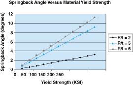
Figure 2The calculated springback angle for a 90-degree bend has a direct and linear relationship to the material's yield strength.
where ai and af are the initial bending angle and final bending angle, respectively. The following formula, which is derived from this relationship, calculates the springback angle:
 |
Where:
Neglecting the effect of a small amount of longitudinal deformation, these formulas can calculate the springback angle for roll forming a high-strength material with a given Young's modulus, yield strength, radius-to-thickness (R/T) ratio, and initial forming angle.
The springback angle increases as the material yield strength increases (see Figure 2). The springback angle is approximately 8 degrees when the yield strength exceeds 200 kilopounds per square inch (KSI) and the R/T ratio is 5. For the same yield strength, the springback angle increases to 10 degrees when the R/T ratio increases to 6. Graphing springback angles versus R/T ratios for two material strengths shows that as the material gauge decreases, the springback angle increases (see Figure 3).
Yield strength increases as a result of work hardening. In addition, the neutral axis shifts as local deformation increases at the bending corner. These changes can affect the calculated springback angle.
Keep in mind that these formulas are based on a pure bending process, press brake forming. Roll forming is far more complex than pure bending, so results calculated from these formulas are just estimates when used for roll forming.
Bending forces deform both the inner and outer fibers at the bending corner by the same amount. The following equation calculates the strains at these fibers:
 |
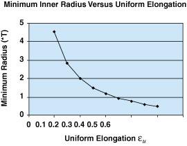
For a given material thickness, the strain increases as the forming radius decreases. When the material exceeds a permissible amount of strain, it can crack. The radius R at which a crack appears on the outer surface of the bending corner is the minimum bending radius, which is often expressed in terms of material thickness.
Two failure conditions determine the minimum bending radius. One is defined as the absolute limit of actual fracture of the material. It is related to the area reduction measured in the tensile testing. The other is defined as localized necking. This is the result of material weakening at the bending corner when elongation in the outer surface exceeds the material's uniform elongation, em. It is expressed in the following equations:
 |
then,
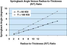
Figure 3The calculated springback angle has a direct and linear relationship to the material's thickness.
 |
Higher strains usually are permissible, because the strain is redistributed in the deformation area. Figure 4shows the estimated minimum corner radius for uniform elongation from 10 percent to 50 percent. The graph shows that 20 percent uniform elongation allows a 2T minimum corner bending radius.
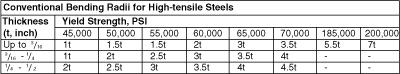
Determining the minimum forming radius is not limited by material failure criteria alone. The forces generated by the forming process also influence the forming radius. Conventional bend radii for eight levels of high-yield-strength materials are shown in Figure 5.
Stresses near the inner and outer surfaces increase when material yield strength increases and the thickness and bending angle remain constant. This stress increase requires an increase in the bending force. However, forming mills have a specific power output at each pass. Increasing the bending forces (power output) at the forming passes can cause forming problems such as marking and tooling wear, which can affect part quality.
High springback, minimum bending radii limits, and high forming forces are just some of the many concerns of forming high-strength materials. Other forming problems, including edge waving, twisting, and end flaring, may occur as well. Tooling engineers should design the tooling with these problems in mind.
Roll forming engineers and tooling engineers should work together to identify the specific requirements for forming mills that are used for high-strength materials. Most roll forming engineers prefer to use the same number of passes to form high-strength materials as they use to form standard materials. This often leads to forming difficulties.
Understanding the limit and effect in forming high-strength material helps both roll forming and tooling engineers in selecting the right tooling design to reduce tooling cost and produce high-quality tooling and formed products.
Baicheng Wen is a retired engineering manager with Roll-Kraft Inc.
References
The Yoder Co., "Roll forming systems for heavy gauge high-tensile steels," Precision Metal (October 1977), pp. 31-36.
Hanhui Li, "Developing a design for cold roll forming: A look at the data collection and flower design stages," The FABRICATOR® (April 1998), pp. 29-37.


The Fabricator is North America's leading magazine for the metal forming and fabricating industry. The magazine delivers the news, technical articles, and case histories that enable fabricators to do their jobs more efficiently. The Fabricator has served the industry since 1970.
start your free subscription
Easily access valuable industry resources now with full access to the digital edition of The Fabricator.

Easily access valuable industry resources now with full access to the digital edition of The Welder.

Easily access valuable industry resources now with full access to the digital edition of The Tube and Pipe Journal.

Easily access valuable industry resources now with full access to the digital edition of The Fabricator en Español.
In this episode of The Fabricator Podcast, Caleb Chamberlain, co-founder and CEO of OSH Cut, discusses his company’s...


