Contributing Writer
Read Part I
 |
Editor's Note: This article, Part II of a two-part series on tube and pipe threading, explores troubleshooting related to threading cutting, insert shape, chip breaker geometry, coatings, and coolants.
An examination of the cutting tools used on the finishing floor to produce threaded tube and pipe reveals how the shape of the insert may affect the tube's deformation caused by residual stress. Generally, the tools used for turning operations are industry-standard shaped cutting inserts such as buttons, squares, and triangles (see Figure 1). Each insert type is available with a positive, negative, or neutral rake angle. The choice of rake angle affects the life of the insert, as well as the amount of energy that is required to force the tool through a cut.
The insert type has a direct impact on quality of the finished surface, tool life, and chip control.
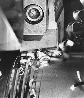
The turning insert, which creates the tapered surface that will receive the pipe thread, must produce a correctly sized, smooth, and chatter mark-free surface so the threading insert can produce the best-quality thread. Although the threading insert recuts the surface produced by the turning insert, the effects of a poorly turned surface can be transferred to the finished thread form.
Many machine and cutting tool conditions can influence the initiation of chatter during cutting. Once initiated, chatter may continue to be generated because of the material hardness, cutting speed, cutting tool geometry, chip breaker configuration, rigidity of the machine and chucks, and the rigidity of the pipe itself. Most often it is the turning tools that initiate chatter marks in the finished thread.
A relationship exists between the pipe OD, its wall thickness, and its ability to support cutting without developing chatter. Pipe loses rigidity if it is manufactured with a thinner wall thickness than is required for its OD. Some pipe sizes that fall within the American Petroleum Institute (API) standards are especially susceptible to chatter because the wall thickness relative to the OD results in a reduced level of structural integrity. Chatter is more of a problem when threading thin-walled pipe than thick-walled pipe. For example, a 95/8-inch- (244-mm-) OD, 0.312-in.- (7.9-mm-) thick pipe often is susceptible to chatter.
The insert shape and the profile of its cutting edge can be used to modify the conditions that lead to chatter. In some cases, the increased cutting force of a button insert may act to dampen chatter. In other cases, the reduced cutting force of a square or triangle insert may limit force-induced instability in the cutting system, thereby reducing chatter.
A discussion of tool life must begin with a look at the cross section of the chip that is generated by each insert type.
 |
| Figure 1 Because a triangle insert leads into the cut at a 90-degree angle, its surface is exposed to the cut the least. |
Figure 1 shows that for a given depth of cut and rate of feed, the button insert's surface is exposed to the cut the most, and the triangle insert's surface is exposed the least. Because the cutting force is distributed over more of the insert's exposed surface, the button insert's useful tool life generally is longest.
The button insert also provides the strongest support for the cutting edge. Also, the button insert enters the cut in a more gradual manner than the other inserts. Because its cutting edge is perpendicular to the longitudinal axis of the pipe, the triangle insert enters abruptly, which creates a greater amount of thermal shock. The cumulative effect of multiple-cut entries under these conditions is to reduce the triangle insert's tool life.
Like the button insert, the square insert enters into the cut more gradually than the triangle insert. Adding a radius to the corner of the square–and the triangle–helps to strengthen the weakest part of these inserts.
Once the insert becomes fully engaged in the cut, the volume of material removed during each revolution of cut is the same for each insert type.
Selecting the proper surface coatings and edge hones can dramatically increase the life of a tool. Correctly applying the right kind of coolant also may improve the tool life of each insert type, but the button insert maintains the longest tool life.
The primary consideration in controlling chip formation during cutting is the material being cut. The chemistry of the tube material determines how the chip is separated from the parent material, as well as how the chip reacts to the heat and stress of the metal removal.
The elements that give steel its machinability may be the same ones that the metallurgist limits during steel production to improve the steel's working characteristics at low temperatures or its corrosion resistance in hostile gas environments. For example, reducing sulfur or phosphorus during steel production may yield desirable characteristics for steel's end use in severe conditions, but also can create tremendous tool life and chip control problems on the pipe finishing floor. These same elements–sulfur and phosphorus–are measured to calculate a machinability factor for steel.
The variability inherent in steel's chemistry and hardness requires an equally variable arsenal of tools to provide the flexibility to apply pipe threads economically.
1. Insert shape. As previously discussed, the type of insert determines the shape of the chip that is produced. Rectangular chips are easier to flex than a chip from a button insert. Variations in a chip's cross-sectional shape give it strength along its longitudinal axis. Just as an I-beam column is stronger than a column constructed of a solid square piece of steel, a chip produced with a nonuniform cross section has greater columnar strength than one produced with a uniform cross section. The nonuniform chip is more difficult to break as it encounters the chip breaker geometry. A reduction in the chip's cross-sectional strength makes it more breakable.
2. Chip breaker geometry. A quick look at a tool catalog will reveal many chip breaker sizes and shapes. No single chip breaker configuration is good for all pipe materials. The best recommendation is to test many configurations and keep notes on which geometry and type combinations work best for which materials. Some materials may yield satisfactory chips with molded chip breakers, while others may require the addition of a mechanical chip breaker.
3. Insert coating. The coating used on an insert can improve its useful life by strengthening the cutting edge of the tool. The coating also can reduce the cratering that is caused when a hard-to-machine material passes over the insert behind the cutting edge.
4. Edge hone. The edge hone is added to the insert before the insert coating is applied to prevent chipping of the cutting edge. Any attempt to modify the hone of a finished insert will tend to remove the coating and reduce the insert's life. While the size and type of hone affect the threading insert the most, the hone also can influence the life of the turning insert. The hone typically applied to turning inserts is a simple radius hone. Threading inserts may require a more complex type, such as a J or even a waterfall hone. The threading insert relies on the hone to help control the built-up edge (BUE), while the turning insert is significantly less susceptible to the effects of BUE.
5. Coolant. Coolant often is purchased simply on the basis of price. Frequently the least expensive coolant is not the most economical. Use of the right coolant may yield increased tool life and improved chip control. It may even affect the amount of stress-induced deformation of the finished product by reducing the energy required to cut the material. Coolant can add lubricity to the sliding surfaces of the machine, reducing maintenance costs. Using the right coolant may not cure all threading problems; however, in a cost-conscious threading operation, fine-tuning should include coolant testing to optimize efficiency.
Results of the testing and comparisons likely will indicate that the economical threading of pipe requires trade-offs. As changes are made to address a problem, sacrifices must be made in other areas. A longer tool life may have to be sacrificed to eliminate chatter, or a machine's cutting speed may need to be reduced to improve chip control. Each threading problem can be addressed by using the tools available. This may require changing insert type, insert substrate, insert coating, or chip breaker configuration.
Good recordkeeping is essential. Once a solution is found for a threading problem, a record of what was done provides a proven solution when the problem arises again. Not only are good records helpful in addressing a threading problem, they also can be used to determine the optimal approach to threading.
Robert White is director of engineering of PMC Industries, 29100 Lakeland Blvd., Wickliffe, OH 44092, 440-943-3300, fax 440-944-1974, RCWhite@PMCIndustries.com, www.pmcindustries.com

The Tube and Pipe Journal became the first magazine dedicated to serving the metal tube and pipe industry in 1990. Today, it remains the only North American publication devoted to this industry, and it has become the most trusted source of information for tube and pipe professionals.
start your free subscription
Easily access valuable industry resources now with full access to the digital edition of The Fabricator.

Easily access valuable industry resources now with full access to the digital edition of The Welder.

Easily access valuable industry resources now with full access to the digital edition of The Tube and Pipe Journal.

Easily access valuable industry resources now with full access to the digital edition of The Fabricator en Español.
In this episode of The Fabricator Podcast, Caleb Chamberlain, co-founder and CEO of OSH Cut, discusses his company’s...