


Contributing Writer
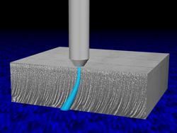
Figure 1 Jet Lag at High Feed Rate
Software serves two functions in abrasive waterjet machining. First, software generally referred to as CAD/CAM is used to transform the design intent into a tool path. This type of software has improved rapidly, and multiple vendors serve this market. Although it is important for easily inputting geometry, this software has little effect on part production cost.
The second function of software is to move the cutting jet to achieve the most accurate part possible in minimal time. This software, which the machine builder supplies with the control, has a huge effect on part cost.
Tremendous variations in the sophistication of available controllers exist. This article describes the software functions in an advanced controller made specifically for waterjet machining in which the functions are broadly covered by patents.1
An early article on this topic, "Software for abrasive waterjet machines"pointed out first that software is critical for managing the jet and, second, that improvements in software can be expected to enhance machine performance. This article examines some of those improvements and the resulting performance increases. But first let's review why software is important.
Those new to abrasive waterjet cutting often wonder why controller software is so important in these machines in comparison to others. The answer is that the abrasive jet is not a rigid tool that must simply be guided along a particular path to make a part. An abrasive-laden jet of water as a tool introduces several kinds of errors when it is moved quickly.
Lag—As the nozzle moves, the bottom of the stream lagsbehind the top. The amount of the lag varies, depending on how quickly the nozzle moves. Lag is important on curves and corners, but not on straight lines.
Striations—As the nozzle moves faster, the bottom portions of the jet begin to oscillate from side to side, producing marks much like flame-cutting marks. These affect surface finish.
Taper—If the nozzle moves quickly, the kerf is widest at the top. As the speed is lowered, taper reduces and eventually reverses, with the kerf becoming widest at the bottom.
Width Versus Speed—As the jet slows down, the kerf becomes wider.
Kickback—The jet shape depends on acceleration as well as speed. A sudden acceleration at an inside corner causes the jet to kick back and gouge deeply into the bottom surface at the corner.
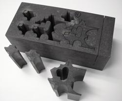
Figure 2 18.2 Minutes Saved With Corner Passing
Figure 1illustrates some of these effects. Advanced control software predicts and compensates for the complex behavior of the jet to achieve precision while producing parts quickly. Recent advances in this software have improved various cutting functions.
Piercing—An abrasive jet can pierce its own start hole for making parts with cutouts. In early machines the jet simply was left in one spot until the material was pierced. This process often took a long time, especially in thick materials. In fact, very thick materials often never pierce with this method, because the incoming jet is so disturbed by the flow coming out from the blind hole.
A great improvement was achieved with the use of wiggle piercing, in which the jet moved back and forth along the path by about 0.10 in. until it pierced through. This allowed the reflected jet to escape without interfering with the incoming jet and cut the pierce time.
Today an even faster piercing method is available. Model testing has shown that there is an optimum pierce length for minimum pierce time, and for any chosen pierce length, there is an optimum traverse speed at which to pierce. Today's software uses a cutting model to predict the optimal pierce distance and speed for piercing any given material. It then grows or shrinks the lead-in as appropriate to be the optimal distance without interfering with other features in the part. If there is not enough room for the fastest possible pierce, the software automatically adjusts the piercing speed, without user intervention, to compensate and shrinks the lead.
Table 1shows the time each method takes to pierce in 1-in. steel. Imagine a piece with 50 pierces. The time saving of 88 seconds per pierce when using the dynamic method rather than the static method cuts the part time by 1.2 hours.
|
Static |
95 sec. |
|
Wiggle |
40 sec. |
|
Dynamic 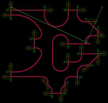
Figure 3 Green Lines Indicate Areas Where Software Is Testing Corner Passing |
7 sec. |
Table 1
Time per Pierce in 1-in. Steel Using Three Methods
External Corners—Normally, programmers or operators slow for corners to avoid the geometry errors caused by jet lag. But there is no need to slow down for an external corner if you have room to go past it. This means that most outside corners can be cut at full speed, as were the parts shown in Figure 2. The jet moves past the corner by at least one jet lag length and then quickly returns to begin the next leg of the corner. Acceleration on the new leg is then limited to avoid kickback damage. The result is that the part is made in 39.4 minutes rather than 57.6 minutes, and the precision of the part is increased by avoiding the slight kerf-width growth that normally would be caused by slowing down.
Corner passing is set automatically by the latest advanced software, so there is no need to program anything special. The corner passing geometry, as well as jet kickback, is optimized for speed and collision avoidance, so that the part does not get damaged by the corner pass (Figure 3). The software even decides automatically whether to use corner passing in the following two cases:
It is possible to disable corner passing when the intent is to utilize both the scrap and the part, such as when doing artistic inlay work.
Internal Corners—Corner passing is not possible in internal corners without damaging the part. Instead, completely different corner models that depend on whether the jet is entering the corner or leaving the corner are used. The jet decelerates hard at the last minute coming into the corner and accelerates softly coming out of the corner to avoid kickback damage.
Taper Control—Usually the jet produces a tapered edge. This can be avoided with two different software strategies. First, by specifying a quality of "minimum taper," the software will slow or speed up the cutting as necessary to provide the minimum amount of taper. In most cases, this means that the cutting speed will be reduced significantly. However, in some cases where reverse taper would otherwise occur, the cutting speed will be increased. In either case, the part will be more precise because of the near elimination of taper.
Although minimum taper quality primarily is a precision benefit, there also is a speed benefit in that the programmer no longer has to guess at the feed rate. Programming time is reduced, and there is no risk of guessing at a speed that is too slow for the desired result. Nevertheless, for some applications, the minimum taper speed is so slow that it's impractical except for especially critical areas on the part.
The second software solution for controlling taper is automatic control of a five-axis machine (Figure 4) that tilts the jet to remove the taper.2The jet moves at the normal speed determined by the surface finish requirement. Then a predictive model is used to predict the taper in the kerf at each portion of the path. Finally commands are generated to tilt the head so that the part edge is vertical and places all taper in the scrap. The result is a square edge (Figure 5).
Purposeful Taper—With the advent of five-axis motion, it has become possible to introduce a small amount of desired taper in the part. Such taper might be used for die relief or draft angle for a casting pattern. In this case, a more complex data structure than for 2-D cutting is required, so that the operator can specify the desired taper at each portion of the path. The software then operates much as it would for a taper-free part, except that the requested additional taper is added to the head motion. A part with purposeful taper is shown in Figure 6.
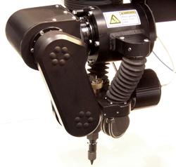
Figure 4 Tilting Head for Taper Removal
There still is room for further improvement in jet cutting software, in terms of both precision and speed. New, more accurate cutting models will better anticipate the jet behavior, allowing the software to correct more accurately for errors inherent in waterjet cutting. Management of striation formation will lead to higher cutting speeds with the same surface quality. Tool offset compensation for speed variation will afford even higher precision.
Software is not an accessory for abrasive waterjets, but is an integral part of the machine. Advanced software dramatically improves system performance by reducing the time to create parts. Shorter part production time lowers part cost through lower abrasive consumption, lower maintenance cost, and delivery of more parts per day. Software plays a central and critical role in advanced waterjet machinery.
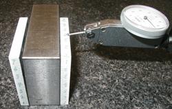
Figure 5 Parts Cut With and Without Taper Control


The Fabricator is North America's leading magazine for the metal forming and fabricating industry. The magazine delivers the news, technical articles, and case histories that enable fabricators to do their jobs more efficiently. The Fabricator has served the industry since 1970.
start your free subscription
Easily access valuable industry resources now with full access to the digital edition of The Fabricator.

Easily access valuable industry resources now with full access to the digital edition of The Welder.

Easily access valuable industry resources now with full access to the digital edition of The Tube and Pipe Journal.

Easily access valuable industry resources now with full access to the digital edition of The Fabricator en Español.
In this episode of The Fabricator Podcast, Caleb Chamberlain, co-founder and CEO of OSH Cut, discusses his company’s...


