


Sensors in the welding environment - Which ones are tough enough for the job?
Sensors play a pivotal role in ensuring production quality in welding environments. The automotive industry, for example, relies heavily on sensors to confirm proper placement of metal car parts before they are fused together. Sensors also can identify a robotic arm's position and signal whether or not the welding mechanism is located correctly before welding begins.
The number of sensors used in a single application varies from a few to a few hundred, depending on the type, scope, and scale of the operation. As much as these sensors are relied upon to ensure accuracy, many are prone to failure in welding environments. With temperatures exceeding 1,200 degrees F, currents from 15,000 to 35,000 amps, and frequent weld flash occurrences, sensors can fail as often as three or four times a day under severe conditions.
Though many sensors are designed for weld resistance, some no longer function after 5,000 weld flashes—and a sensor located within 10 inches of a weld tip can easily be exposed to 1,000 to 2,000 flashes per day (see Figure 1).
A single sensor failure causes just a few minutes of downtime. But when several devices falter from the harsh welding conditions, productivity significantly decreases as replacement and installation costs skyrocket. Without these sensors, however, the production loss that results from improper welding could cost companies even more.
To solve this dilemma, sensors are constructed with rugged housings, encapsulated electronics, and other features to help them resist the harsh welding environment. By using properly designed sensors in welding applications, manufacturers can reliably errorproof production lines without excessive downtime or high replacement costs.
Sensors in the Assembly Process
Automated production lines are optimized to ensure the highest level of accuracy, but mistakes still happen. Metallic components might be placed on the assembly line in the wrong order or orientation, making it likely for a robotic welding arm to fuse these parts incorrectly.
In automotive applications, if a robotic clamp holding metal car parts is positioned at the wrong angle, vehicle components might be generated incorrectly. Or a single component, such as a sheet of metal, might not contain all the nuts, bushings, and spacer sleeves needed to complete the assembly process, and undergoing welding in this condition would result in a rejected part.
To prevent rejects, proximity sensors can be positioned on a conveyor so that, as metal parts are transferred down the line, the sensors detect whether or not the correct components are in their proper places. The sensors then send a pass/fail output to signal if welding can begin. A similar solution is employed in robotic clamping applications; in these situations, the sensors determine not only component position, but also jaw and gripper position (open or closed).
Proximity sensors designed to withstand harsh manufacturing environments, such as a welding cell, provide increased reliability and data collection capabilities because their rugged construction allows them to be placed near the cylinder on the robotic arm mechanism. Once configured, a sensor can detect the piston's movement within the cylinder—which corresponds to the angle the jaws/grippers open—and signal the gripper to open to a precise position for the component being held.
Meanwhile another sensor can be placed into a groove within the actual jaw/gripper to confirm this component is moved to the proper location. This custom embedding helps protect the sensor from environmental conditions and provides complementary errorproofing for part-in-place applications.
For identifying smaller components such as nuts or bushings on sheet metal, one solution is to use a magnetic-inductive weld nut sensor, which can be programmed to differentiate between the nut or bushing and the sheet metal on which it is placed (see Figure 2). The sensor is mounted through a hole in the sheet metal, and when a weld nut is present, the sensor produces an output that initiates the welding process. It uses simple go/no-go operation and has a housing optimized for welding environments.
Operation in Harsh Conditions
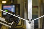
The level of weld resistance a sensor needs depends largely on how closely the sensor is located to the welding mechanism. Any sensor exposed to weld flash will experience some negative effects, but sensors positioned within inches of the weld tips must withstand 10,000 to 20,000 flashes without failure. This performance can be difficult to achieve because of the strong electromagnetic fields that weld flashes produce, which can cause a proximity sensor to trigger falsely. Plus, weld slag or spatter accumulates and eventually causes the sensor to malfunction.
To resist these environmental elements, sensors use a combination of specialized construction and numerous protection techniques (see Figure 3). Some sensors provide weld resistance by offering temperature compensation to operate reliably in high-temperature welding environments. A stainless steel front cap design and copper housing construction make these sensors more resistant to mechanical damage. Some sensor bodies also are made from a material that can withstand slag and spatter and resist the electromagnetic field.
Another technique is to incorporate fitted steel covers into the sensor housing before sealing the sensor. This makes it impervious to physical damage from the side and weld damage from the front when combined with weld-resistant front caps or coatings. Manufacturers also can incorporate stainless steel sleeves to cover the sensor and help protect it from mechanical damage.
Factor 1 Sensing
Even with a rugged design and fitted covers or coatings, sensors still can fail on a somewhat regular basis. Another way to minimize replacement costs is to employ sensors that can be applied in multiple applications rather than purchasing specialized sensors that are applicable only in certain production areas.
Sensors that incorporate factor 1 technology combine this universality with electromagnetic resistance. Factor 1 sensors use separate, independent sender and receiver coils on a printed circuit board. This allows the sensors to detect ferrous and nonferrous metals at the same range without adjustment and provide a longer overall sensing range. Because they can be used with a broad range of metals in a variety of applications, they also reduce sensor inventory. (Before factor 1 sensing was introduced, engineers had to adjust the sensing range of inductive proximity sensors to accommodate the correction factors associated with different metals. For example, nonferrous metals such as copper, lead, stainless steel, and aluminum have varying correction factors, ranging from 0.25 to 1.00.)
Most factor 1 sensors are made with a nonferrite core, so they are inherently immune to magnetic field interference. This design allows them to operate at a high switching frequency and makes them especially suitable for electric welding operations, lifts, and electronic furnaces.
The coil technology used in these sensors allows for limited or fully recessed mounting, with little or no decrease in sensing range to reduce the risk of physical damage. This same technology allows some factor 1 sensors to be incorporated into multiple housing styles, making them suitable for use in compact areas such as under a conveyor belt.
From weld resistance to factor 1, sensors employ technology to deliver accurate, long-lasting operation, even in challenging welding environments. When properly applied, these systems reduce downtime and replacement costs while optimizing production.
About the Author
About the Publication

subscribe now

The Fabricator is North America's leading magazine for the metal forming and fabricating industry. The magazine delivers the news, technical articles, and case histories that enable fabricators to do their jobs more efficiently. The Fabricator has served the industry since 1970.
start your free subscription- Stay connected from anywhere

Easily access valuable industry resources now with full access to the digital edition of The Fabricator.

Easily access valuable industry resources now with full access to the digital edition of The Welder.

Easily access valuable industry resources now with full access to the digital edition of The Tube and Pipe Journal.

Easily access valuable industry resources now with full access to the digital edition of The Fabricator en Español.
- Podcasting

Cameron Adams of Laser Precision, a contract metal fabricator in the Chicago area, joins the podcast to talk...
- Trending Articles
1
What software automation means for custom fabrication

2
Why employee-owned companies make sense in manufacturing

3
Nucor’s weekly steel price announcement continues to rattle markets

4
Press brakes, panel benders, and flat blank calculations
5
Washington artist creates life-size elk sculptures