


The heat is off
Why hydroforming makes sense in heat exchanger manufacturing
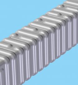 |
| Figure 1 The heat exchanger shell requires forming numerous complex shapes in a short cycle time. |
The process of developing a hydroformed part is similar in many ways to developing a stamping. Factors that must be considered include part geometry (the amount of deformation required determines if the part can be hydroformed without splits or wrinkling); material properties (elongation, formability, yield, and strength); the pressure and press force required to form the part; tube or blank dimensions; and blank preparation and lubrication.
But how do fabricators decide which manufacturing process to use to produce a particular part? The following example describes how a company might evaluate stamping versus hydroforming a heat exchanger.
Heat Exchanger Application
Making the heat exchanger shell shown in Figure 1 requires stamping the part in two halves and then welding the halves together. This process requires two stampings, as well as time to weld and test the two seams.
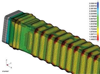 |
| Figure 2 The simulation's thickness prediction is evaluated and the results submitted for analysis in the customer's fatigue simulation software. |
While hydroforming offers many advantages, one of the most important is that it can form a complex shape from a simple tubular blank, eliminating the need for additional steps such as cutting and welding. This reduces part cost and weight and may improve strength and stiffness.
If a rectangular blank could be produced by press brake bending, it would require only one welded seam. The company thinks that hydroforming might provide better dimensional control of the finished part. However, for hydroforming to be cost-effective, the cycle time needs to be 30 seconds or less.
The application requires that the part be fabricated from 304 stainless steel and that it operate under continuous cyclic pressures, which raises significant concerns regarding fatigue life. A requirement is for the part to have infinite fatigue life at the pressures it will be subjected to. The customer's fatigue simulation shows that the fatigue life of the part would be affected by thinning occurring during the forming process, so an accurate prediction of thinning is important. The goal is to keep thinning under 20 percent.
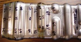 |
| Figure 3 The prototyped part shows thickness measurements along the complexly formed shapes. |
Finite Element Analysis. The customer's CAD file is used to develop a computer model of the tool surfaces. The simulation is performed using ETA Software's Dynaform. A material model for 304 stainless steel is chosen from the software package's library of material properties.
Hydroforming pressure and end-feed profiles are developed and programmed in the simulation package. Simulations are performed to arrive at a process that produces a heat exchanger that meets both strength and thinning requirements (see Figure 2).
The Results. Once an acceptable simulation is achieved, the results are used to design a die and docking rods. The simulation also is used to determine that the part requires a 1,000-ton press and hydroforming pressure of 25,000 pounds per square inch. Approximately 50 prototype parts are successfully produced for testing and analysis. To verify simulation results, parts are sectioned and measured to determine overall dimensions and thinning (see Figure 3), and then the results are compared with the simulation predictions (seeFigure 4).
| Thickness Data for Part 38 | ||||||||||||||||||||||||||||||||||||||||||||||||||||||||||||||||||||||||||||||||||||
|
||||||||||||||||||||||||||||||||||||||||||||||||||||||||||||||||||||||||||||||||||||
| Figure 4 The actual thinning of the hydroformed part closely matches the thinning predicted by the finite element simulation. The simulation predicted the actual results within 5 percent. Furthermore, analysis shows that thinning of less than 20 percent predicted by the simulation is achieved. |
In addition to thinning, the customer is concerned about the tolerance of the final inside dimensions. Measurements of the prototypes indicate that the inside dimensions are within 0.005 inch of nominal for a part approximately 4 by 5 in. This is considered a good result. Prototyping also shows that a cycle time of 30 seconds or less is achievable.
Tom Driggers is president/CEO of Interlaken Technology Corp., 8175 Century Blvd., Chaska, MN 55318, 952-942-7499, fax 952-942-7599, www.interlaken.com.
About the Author
About the Publication

subscribe now

The Tube and Pipe Journal became the first magazine dedicated to serving the metal tube and pipe industry in 1990. Today, it remains the only North American publication devoted to this industry, and it has become the most trusted source of information for tube and pipe professionals.
start your free subscription- Stay connected from anywhere

Easily access valuable industry resources now with full access to the digital edition of The Fabricator.

Easily access valuable industry resources now with full access to the digital edition of The Welder.

Easily access valuable industry resources now with full access to the digital edition of The Tube and Pipe Journal.

Easily access valuable industry resources now with full access to the digital edition of The Fabricator en Español.
- Podcasting

In this episode of The Fabricator Podcast, Caleb Chamberlain, co-founder and CEO of OSH Cut, discusses his company’s...
- Trending Articles
1
Zekelman Industries to invest $120 million in Arkansas expansion

2
3D laser tube cutting system available in 3, 4, or 5 kW

3
Corrosion-inhibiting coating can be peeled off after use

4
Brushless copper tubing cutter adjusts to ODs up to 2-1/8 in.

5
HGG Profiling Equipment names area sales manager
