


Fabricating antenna components
Precision bending, end forming are necessary for strong, clear communications

Imagine driving down a country road, rounding a bend, and coming across a couple of cars in the ditch. You’re the first person on the scene so you use your mobile phone to call emergency services. In a minute or so a police car and an ambulance are on their way.
Dialing 911 isn’t a big deal, but getting your telephone signal routed to the emergency responders is. Your call went to the closest cell phone tower, and from there it was directed to another tower, and another, until it reached the closest town, and then to an operator at the emergency services desk.
The system is mainly electronic, but a key component in the cell phone tower is a tube that connects the transmitter to the antenna. Because the transmitter’s output is a wave of electromagnetic energy and the tube guides it to the antenna, the tube is called a waveguide. The waveguide’s shape is critical for strong, clear transmission and an audibleconversation.
Radio Frequency Systems, Meriden, Conn., builds cell phone tower systems, and rather than outsourcing the fabrication processes, it makes most of its antenna components in-house.
OEM or Fabrication Shop? Both.
A visitor at RFS expecting clean rooms, armies of workers with soldering irons assembling circuit boards, and conversations laced with lots of electronics jargon would be surprised to see that RFS looks a lot like a metals shop. It unwinds large spools of copper wire and wraps them in a protective sheath on equipment that looks a lot like a tube or pipe mill. To make a dish-shaped antenna, itspins a 6-, 8-, 10-, or 12-ft.-dia. sheet and forms it into a parabola. It also uses a tube bender and an end former for making waveguides.
Waveguide Materials and Design. Most fabricators work with materials such as 1018 mild steel, 316 stainless steel, or 6061 aluminum, so the metals used in waveguides, such as 90/10 cupronickel (88.6 percent copper, 10 percent nickel, and a bit of manganese and iron) or 70/30 brass (70 percent copper, 30 percent zinc), might seem foreign.
Although copper is a soft metal, anyone who thinks that it’s easy to form might be surprised to learn that it isn’t necessarily so. Malleability (compressibility) and ductility (stretchability) don’t always go hand-in-hand. While pure copper is malleable—anyone who has placed a penny on a railroad track knows this—it’s not all that ductile, so bending a copper alloy requires as much care asbending other metals.
Furthermore, some of the design considerations are different for waveguides than for other manufactured products. For example, transmission efficiency is key. In a radio frequency (RF) system, the efficiency is determined by how easily the transmitter’s output, the electromagnetic wave, flows through the waveguide. In a perfect system, all of the energy from the transmitter travels through thewaveguide and exits the antenna. However, a difference in the electrical characteristics between the waveguide and the antenna, also called an impedance mismatch, causes some of the energy to be reflected back toward the transmitter. The efficiency is measured by the voltage standing wave ratio (VSWR). The goal is to minimize the VSWR, which is the ratio of reflected energy totransmitted energy.
Making a waveguide is a little more tricky than making a common fabricated component, such as a lawn mower handle or a chair frame. A waveguide’s dimensional characteristics have a big impact on how it performs. For a lawn mower handle, an 89- or 91-degree bend would be acceptable; the assembler can use a little force to fit the handle onto the mower and it will still function as a handle. Foran antenna, the bends have to be perfect to minimize the VSWR. The end forming likewise has to be precise. The waveguide’s interior must remain clean and dry, so a snug fit for the dust cap is necessary to keep out dust, dirt, debris, and moisture.
Cost is a critical issue too. Fabricators who reluctantly pay $800 per ton for hot-rolled steel would probably turn pale at the thought of working with a metal that costs $4.25 per pound, or $8,500 per ton.
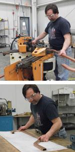
Figure 1: Successful bending is the first step in fabricating a waveguide. It requires one 180-degree bend and two 45s. The straight sections near the tube ends must be aligned with each other to achieve the best radio frequency (RF) transmission and reception.
Despite the peculiarities of manufacturing waveguides, fabricators would recognize the equipment RFS uses to bend and form the lengths of copper tubing.
Shaping Copper. The first stop is a Pines #2 bender, fitted out with tooling to handle rectangular shapes (see Figure 1). Working from tangent lines marked on the tube’s surface, the bender operator first forms a 180-degree bend at one end of the tube. After two more bends, the waveguide has a hooked shape.
“Whether you’re bending brass or copper makes a big difference,” said Senior Manufacturing Engineer James Moquin. “Copper stretches a little bit more than brass, so your second tangent point is closer to the first, anywhere from ¼ to 3⁄8 of an inch,” he said.
A successful bend is a matter of proper material hardness. RFS has received material that was too hard, resulting in cracks that develop during the bending process. It has also received material that was too soft to be useful.
“We had some material that was so soft that it couldn’t support its own weight,” Moquin said. “When you lifted a 12-ft. length, it started to collapse right away. We could have bent it and flared it, but it wouldn’t have been very stable in the antenna,” he said, referring to the rigidity needed to withstand weather conditions such as high winds and storms.
The second workstation is a custom ram-type end former from Winton Machine Co. (see Figure 2). Designed to secure the U-shaped end of the waveguide, the machine is set up for quick die change; it requires just a minute or so and an Allen wrench to change from one die to another.
The end forming process further stresses the material, but things rarely go wrong at this stage. By the time the material gets to the end former, it has passed a quality control inspection and has been stretched to a 180-degree bend, so it has enough ductility for the last step.
“If we can bend it, we can flare it,” Moquin said.
The final steps involve tuning the waveguide. The maximum allowable VSWR is so low that each waveguide must be adjusted manually so it has the right amount of impedance. First, a technician drills a few holes in the waveguide and inserts threaded screws into the holes. After connecting the waveguide to an RF source and an oscilloscope to monitor the VSWR, the tuner adjusts the depth of eachscrew to minimize the VSWR. If the VSWR is still too high, he makes some changes to the waveguide’s walls. He grips the waveguide with a pair of pliers and, while monitoring the oscilloscope, applies a little pressure here and there along the length of the tube, slightly modifying the wall as he goes until the VSWR is within the specification.
Beyond 3G
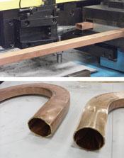
Figure 2: RFS’s end former (top) is set up to make two hits to flare the ends of rectangular copper tubing (bottom) to make waveguides. The first hit does about half the work and the second hit does the rest.
Mobile phones have been affordable for years, so you might think that the mobile tower market is saturated and that the phone tower systems business would taper off. And you’d be wrong. Mobile phone standards evolve continuously. The first-generation (1G) network of the 1980s, which was analog, was swept aside in the 1990s by the 2G network, which was digital. This was followed by 3G (firstdeployed in 2001), and then 4G (defined in 2009).
All of these upgrades increase the data transfer capacity and have additional capabilities that require more sophisticated hardware, so the future is clear and bright for RFS.
About the Author

About the Publication

subscribe now

The Tube and Pipe Journal became the first magazine dedicated to serving the metal tube and pipe industry in 1990. Today, it remains the only North American publication devoted to this industry, and it has become the most trusted source of information for tube and pipe professionals.
start your free subscription- Stay connected from anywhere

Easily access valuable industry resources now with full access to the digital edition of The Fabricator.

Easily access valuable industry resources now with full access to the digital edition of The Welder.

Easily access valuable industry resources now with full access to the digital edition of The Tube and Pipe Journal.

Easily access valuable industry resources now with full access to the digital edition of The Fabricator en Español.
- Podcasting

Seth Feldman of Iowa-based Wertzbaugher Services joins The Fabricator Podcast to offer his take as a Gen Zer...
- Trending Articles
1
Zekelman Industries to invest $120 million in Arkansas expansion

2
3D laser tube cutting system available in 3, 4, or 5 kW

3
Corrosion-inhibiting coating can be peeled off after use

4
Brushless copper tubing cutter adjusts to ODs up to 2-1/8 in.

5
HGG Profiling Equipment names area sales manager
