New Product Development and In-Die Engineer
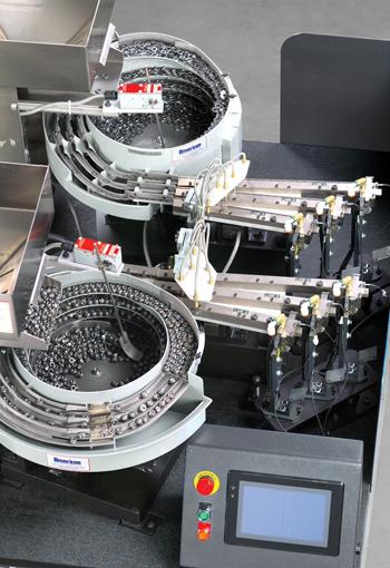
Figure 1: In-die fastening systems can be configured to handle one or multiple types of fasteners.
Most stamped components eventually become part of an assembly, and, in most cases, the assembly requires fasteners. Over the years self-clinch fasteners have ranked high on the list of hardware choices, in part because they become a permanent part of an assembly and reduce the amount of loose hardware.
Fastening also has benefited from in-die technology, combining stamping and fastener insertion in one operation, leading to less labor, simpler material handling, less scrap, better floor space utilization, and increased throughput and productivity (see Figure 1).
It also reduces work-in-progress. A secondary operation typically is much slower than stamping. Consequently, stockpiles of parts are run off the die and then sit in queue waiting for fastener processing. In-die systems can eliminate these stockpiles to increase inventory turns.
As with any technology, though, in-die fastening can have its problems, and for a variety of reasons. But understanding an in-die system’s design and function can empower you with the appropriate knowledge and remedial actions to resolve these problems and optimize performance.
In general, troubleshooting focuses on four key aspects: the fasteners, the feed system, the in-die tools (often referred to as insertion heads), and the control system.
Among all the variables of an in-die fastener insertion system, the dimensional characteristics of the fastener itself is one of the most critical (though hardness and plating sometimes come into play). As with all manufactured parts, tolerances are key. Your in-die system must be able to accommodate the fasteners to their maximum and minimum tolerance range to prevent the fastener from jamming.
Also be sure to account for stacked tolerances. One fastener may be just within the tolerance range, but say that fastener works within an assembly requiring many other fasteners, all of which also happen to be just within the tolerance range. After all parts are fastened together, these fastener tolerances stack up. The stack-up tolerance range should be greater than the individual fastener’s tolerance range.
Considering this from the beginning can avoid a lot of wasted effort. For instance, you may modify components, such as feed rails and die tools, to accept a specific size range of fasteners, only to discover that the next lot of fasteners will not feed because of the changes just made. Subsequently, you repeat the modification over and over.
You can eliminate this by assessing the tolerances for the various features of the fastener in concert with the stacked tolerances of critical dimensions. Such an approach will define the parameters in terms of what will, and what will not, feed in the system.
The feed system must be robust because of the harsh environment in which it will operate. It must be reliable over time, especially given speed parameters and the volume of fastener insertions over the life of a program.
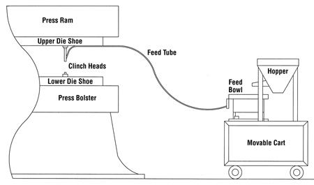
Figure 2: In-die fastener feeding systems should be portable and flexible. In this typical setup, the feed system sits on a cart that can be moved from press to press as required.
It also should be mobile and flexible. You should be able to cost-effectively expand and adapt the system to new or additional applications. And you should be able to place it in production quickly and remove it when not in use. This allows you to move it from press to press as production requirements change (see Figure 2).
Quick-disconnect features let you streamline changeover time. This also means that if a problem occurs during a run, you can quickly change over or disconnect the in-die fastener feed system so that other operations can run on the equipment.
Of course, to head off problems, consider troubleshooting in advance by running the feed system at production speed offline. You also can make test runs before production.
Once an in-die fastener feed system is up and running, you may find that the most common problems involve jamming, slow feed rates, and upside-down or misoriented fasteners.
Jamming. Causes of jams include dimensional changes to the fasteners, worn components such as feed rails and shuttles, and amplitude changes to the in-die system’s vibratory bowl or inline drives. While you can measure and visually inspect for fastener dimensional changes and worn components, amplitude changes of the vibratory bowl or drives can be more difficult to pinpoint.
Factors to consider include the number of fasteners staged in the bowl and voltage changes in the electrical supply. If too many or too few fasteners are staged in the bowl, the system may run too slow or too fast, respectively. Voltage changes can produce a similar effect. Voltage can fluctuate from changes in the load on the electrical line—say, when other machines on the same circuit cycle on and off. These voltage fluctuations affect the amplitude of the vibratory bowl.
If the bowl is running too fast or slow, first try adjusting the amplitude of the vibratory bowl to compensate. If you can’t find an ideal adjustment, keep the number of fasteners in the bowl more consistent (that is, a narrower high/low range). If necessary, connect the in-die system to a dedicated electrical supply line.
Slow Feed Rates. Slow feed rates can be caused by vibratory amplitude fluctuations as well as several other factors. In pneumatic systems, the fastener-blower’s time settings can affect feed rates. In these systems, the fasteners are fed to the die individually as the press strokes. If blower times are excessive, less time may be available for fastener staging, and the shuttle must wait for the blower time to end before the next fastener can be fed from the bowl.
Be sure to set blower times carefully. You need to not only achieve consistent fastener delivery to the tool heads in the die, but also achieve the greatest possible feed rates.
Broken bowl springs also may contribute to slow feed rates. These flat, hardened springs usually break at their attachment points, and the cracks can be difficult to detect since they often are hidden under the spring’s retaining screw heads or clamp plates. Inspect the springs carefully for fatigue cracks.
Upside-Down or Misoriented Fasteners. If you have a well-designed and -maintained system, it should not feed upside-down or misoriented fasteners. At the very least, each track should contain a feature to prevent incorrectly oriented fasteners from passing to the die.
The usual culprits are worn or missing tooling in the feed system or dimensionally incorrect fasteners. If the tooling features are worn or have been removed, upside-down fasteners could be fed to the die, especially if they are clinch nuts, which have very similar tops and bottoms.
In-die tools require close scrutiny. Similar to dies, in-die tools usually are built on conventional principles. But because of specific characteristics of the workpiece or die in which they operate, each in-die tool set may need to be uniquely crafted for the application.
In-die tool problems can cause inaccurate fastener positioning, poor clinch performance, or fastener damage. Common causes are substandard fasteners, tool wear, tool damage, as well as misalignment between in-die tooling to the stock strip. Off-center installation can damage fasteners and hurt their performance. For optimal performance, the fastener should be properly seated with the clinch features fully embedded into the stock strip and aligned concentric within its respective hole.
If insertion-related problems occur, first verify that the fasteners are within tolerance, since they are guided by either their external or internal features, depending on the fastener type. If they fall within acceptable parameters, then check the running areas within the tools for excessive wear or damage.
Problems may be traced further to potential misalignment of the tool heads. Confirm their alignment by placing modeling clay or a similar soft material on the end of the tool head and then closing the die. The impression made between the tool head and the anvil will tell you the alignment story.
The camber in the stock strip also can cause some positioning problems. Proper alignment of guide rails and piloting ensures consistent quality, so be sure to check for worn rails or pilots. If the insertion station is not properly piloted, more pilots may be necessary to hold the strip in position during fastener insertion. Once the fastener is inserted in the stock strip, you can confirm proper insertion by verifying that it was installed to the drawing requirement and by conducting push-out and torque-out tests.
A well-designed and -functioning control system can serve as a reliable asset for troubleshooting. The control system effectively represents the backbone that ties all subsystems together, including the feed system, the die, and the press.
The control system also serves as a highly sophisticated communications resource for the press operator and die technicians. Touchscreens provide immediate online assistance. When properly configured and programmed, such technology can display troubleshooting text or graphics immediately after a fault occurs. Presented in various ways and languages, the display shows information about the fault, how to correct it, and how to restart the system. This can shorten troubleshooting time as well as the learning curve of inexperienced operators.
In-die fastening systems can help your operation achieve new levels of capability and performance. With a comprehensive understanding of design intent combined with a working knowledge of a system’s capabilities, you can avoid the common pitfalls on the path toward consistent success.
holder

The Fabricator is North America's leading magazine for the metal forming and fabricating industry. The magazine delivers the news, technical articles, and case histories that enable fabricators to do their jobs more efficiently. The Fabricator has served the industry since 1970.
start your free subscription
Easily access valuable industry resources now with full access to the digital edition of The Fabricator.

Easily access valuable industry resources now with full access to the digital edition of The Welder.

Easily access valuable industry resources now with full access to the digital edition of The Tube and Pipe Journal.

Easily access valuable industry resources now with full access to the digital edition of The Fabricator en Español.
Patrick Brunken, VP of Addison Machine Engineering, joins The Fabricator Podcast to talk about the tube and pipe...